
Disk drive comprising a spindle motor employing anionic/cationic lubricant to reduce disk surface potential

Active Publication Date: 2007-02-20
WESTERN DIGITAL TECH INC
View PDF15 Cites 110 Cited by
  • Summary
  • Abstract
  • Description
  • Claims
  • Application Information

AI Technical Summary

Benefits of technology

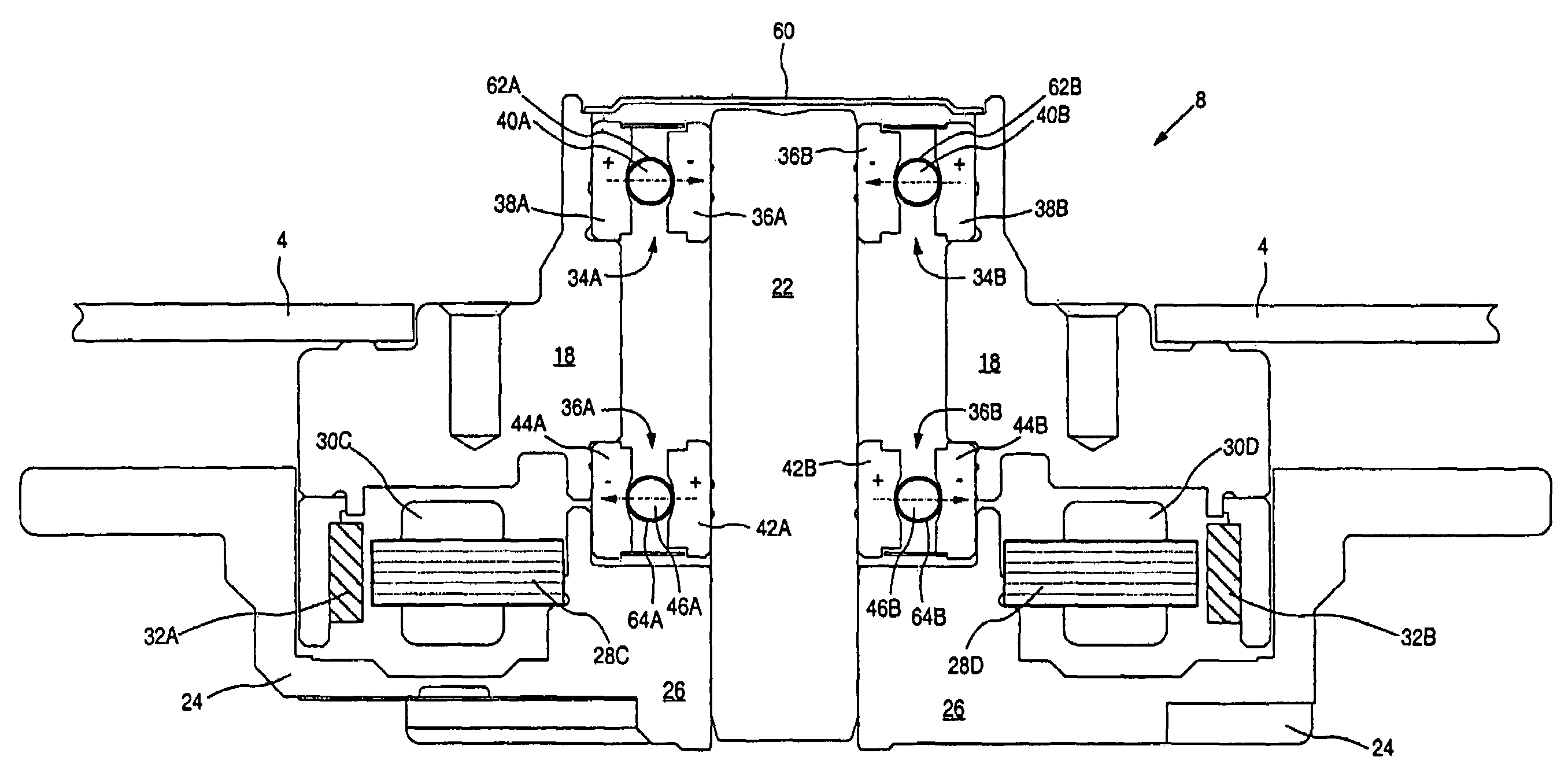
[0008]The present invention may be regarded as a disk drive comprising a disk, a head actuated over the disk, and a spindle motor for rotating the disk. The spindle motor comprises a rotating component, a stationary component, and a first and second bearing assembly disposed between the rotating component and stationary component for rotating the rotating component about the stationary component, wherein the disk is attached to the rotating component. The first bearing assembly comprises a first stationary component surface and a first rotating component surface, and an anionic lubricant is disposed between the first stationary component surface and the first rotating component surface such that a first voltage forms between the first stationary component surface and the first rotating component surface when the rotating component rotates about the stationary component. The second bearing assembly comprises a second stationary component surface and a second rotating component surface, and a cationic lubricant is disposed between the second stationary component surface and the second rotating component surface such that a second voltage forms between the second stationary component surface and the second rotating component surface when the rotating component rotates about the stationary component, wherein a polarity of the second voltage being opposite a polarity of the first voltage to thereby reduce the potential at the disk surface.
[0013]The present invention may also be regarded as a spindle motor for rotating a disk in a disk drive, the disk drive comprising the disk and a head actuated over the disk. The spindle motor comprises a rotating component, a stationary component, and a first and second bearing assembly disposed between the rotating component and stationary component for rotating the rotating component about the stationary component. The rotating component for attaching to the disk. The first bearing assembly comprises a first stationary component surface and a first rotating component surface. An anionic lubricant is disposed between the first stationary component surface and the first rotating component surface such that a first voltage forms between the first stationary component surface and the first rotating component surface when the rotating component rotates about the stationary component. The second bearing assembly comprises a second stationary component surface and a second rotating component surface. A cationic lubricant is disposed between the second stationary component surface and the second rotating component surface such that a second voltage forms between the second stationary component surface and the second rotating component surface when the rotating component rotates about the stationary component. A polarity of the second voltage being opposite a polarity of the first voltage to thereby reduce the potential at the disk surface.

Problems solved by technology

Because the disk is attached to the rotating component, any voltage that builds between the rotating component and the stationary component raises the potential at the surface of the disk which can damage the head, particularly magnetoresistive (MR) heads.
However, the complexity and component count of ferro-fluidic seals increase the cost of the spindle motor as well as the likelihood of failures due to defects.

Method used


Image

  • Disk drive comprising a spindle motor employing anionic/cationic lubricant to reduce disk surface potential
  • Disk drive comprising a spindle motor employing anionic/cationic lubricant to reduce disk surface potential
  • Disk drive comprising a spindle motor employing anionic/cationic lubricant to reduce disk surface potential

Examples


Embodiment Construction

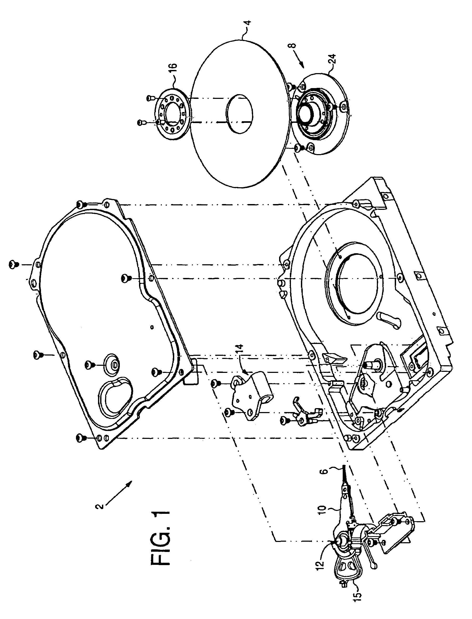
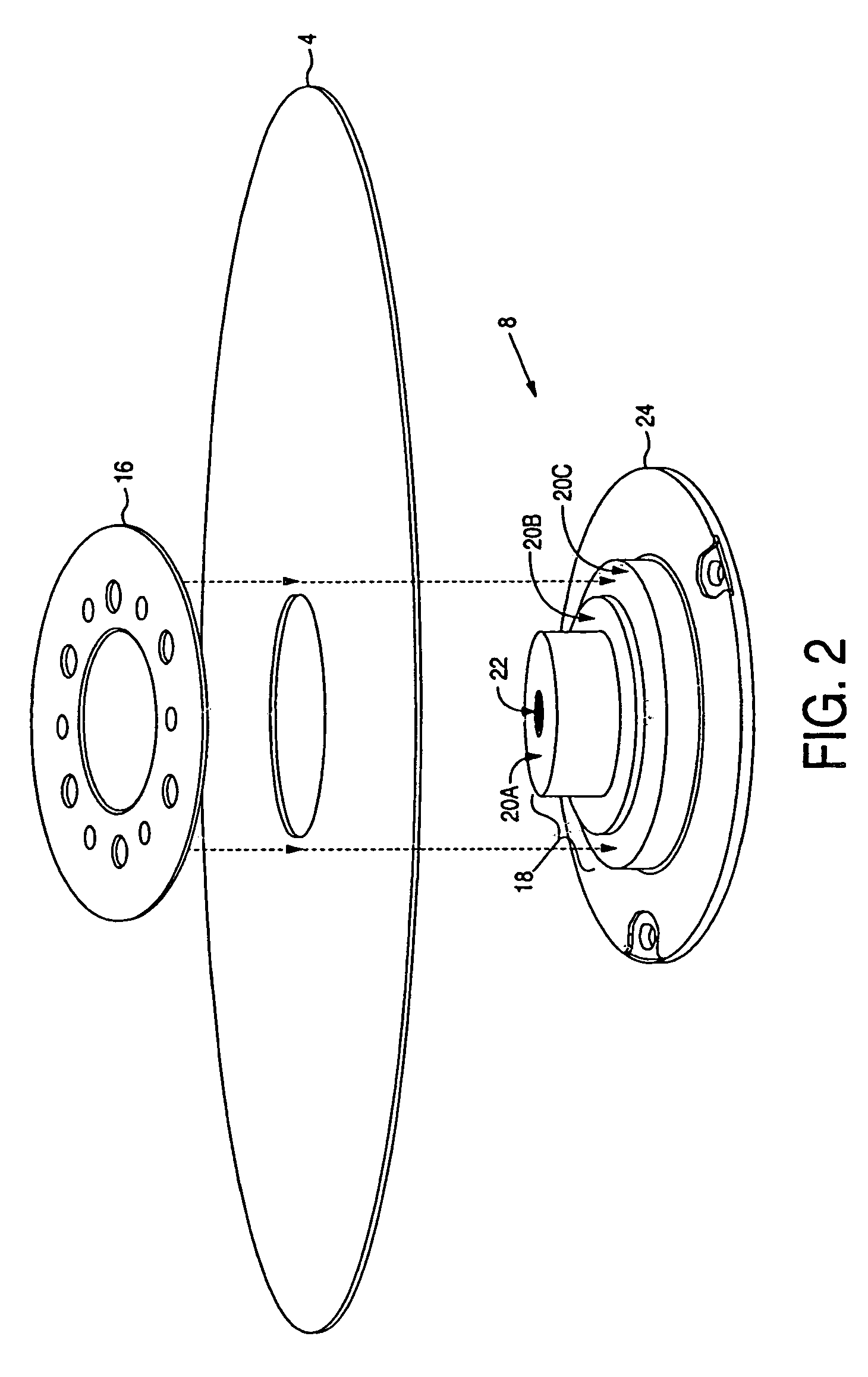
[0021]FIG. 1 shows an exploded view of a disk drive 2 according to an embodiment of the present invention comprising a disk 4, a head 6 actuated over a surface of the disk 4, and a spindle motor 8 for rotating the disk 4. The spindle motor 8 comprises a rotating component, a stationary component, and a first and second bearing assembly disposed between the rotating component and stationary component for rotating the rotating component about the stationary component, wherein the disk is attached to the rotating component. The first bearing assembly comprises a first stationary component surface and a first rotating component surface, and an anionic lubricant is disposed between the first stationary component surface and the first rotating component surface such that a first voltage forms between the first stationary component surface and the first rotating component surface when the rotating component rotates about the stationary component. The second bearing assembly comprises a sec...


PUM


Abstract

A disk drive is disclosed comprising a disk, a head actuated over the disk, and a spindle motor for rotating the disk. The spindle motor comprises a rotating component, a stationary component, and a first and second bearing assembly disposed between the rotating component and stationary component for rotating the rotating component about the stationary component, wherein the disk is attached to the rotating component. The bearing assemblies comprise a stationary component surface and a rotating component surface having a lubricant disposed there between. The first bearing assembly employs an anionic lubricant such that a first voltage forms between the stationary component surface and the rotating component surface when the rotating component rotates about the stationary component. The second bearing assembly employs a cationic lubricant such that a second voltage forms between the stationary component surface and the rotating component surface when the rotating component rotates about the stationary component. A polarity of the second voltage being opposite a polarity of the first voltage to thereby reduce the potential at the disk surface.

Description

BACKGROUND OF THE INVENTION[0001]1. Field of the Invention[0002]The present invention relates to disk drives for computer systems. More particularly, the present invention relates to a disk drive comprising a spindle motor employing anionic / cationic lubricant to reduce disk surface potential.[0003]2. Description of the Prior Art[0004]Disk drives employ a spindle motor for rotating a disk while a head writes data to and reads data from the disk. The spindle motor comprises a plurality of permanent magnets and a plurality of windings. When the windings are energized with current according to a commutation sequence the resulting magnetic flux interacts with the magnetic flux of the permanent magnets to rotate a rotating component about a stationary component. Because the disk is attached to the rotating component, any voltage that builds between the rotating component and the stationary component raises the potential at the surface of the disk which can damage the head, particularly ma...

Claims


Application Information

Patent Timeline
IPC IPC(8): G11B33/14
CPCG11B19/022G11B25/043
Inventor SUBRAHMANYAM, JAI N.CHUE, JACK M.
Owner WESTERN DIGITAL TECH INC
Learn More