Headset with adjustable microphone boom

a microphone and adjustable technology, applied in the field of headsets with adjustable microphone booms, can solve the problems of not being able to secure in any fixed position, and placing great demands on the part of users, and achieve the effect of good and durable connection

Inactive Publication Date: 2007-02-20
GN NETCOM
View PDF8 Cites 15 Cited by
  • Summary
  • Abstract
  • Description
  • Claims
  • Application Information

AI Technical Summary

Benefits of technology

[0016]As disclosed in claim 5, for reasons of advantageous production technique, it is an advantage if the friction coupling is configured as a stamped-out part of the plate.
[0017]To ensure a good and durable connection between the microphone boom's bearing part and the stamped-out part, as disclosed in claim 6, it is advantageous if the stamped-out part consists of two plates which are arranged to accommodate the friction part between two of their surfaces. In this way, a secure grip is obtained around the friction part which, due to the spring effect from the two plates against the friction part, maintains a force sufficient to secure the friction part after long-time use.

Problems solved by technology

Such a swinging to and from the cheek must naturally be able to be effected during the whole lifetime of the headset, and without the microphone boom becoming loose with the result that it cannot be secured in any fixed position.
This requirement places great demands on the manner in which the microphone boom is coupled to the headset.

Method used


Image

  • Headset with adjustable microphone boom
  • Headset with adjustable microphone boom
  • Headset with adjustable microphone boom

Examples


Embodiment Construction

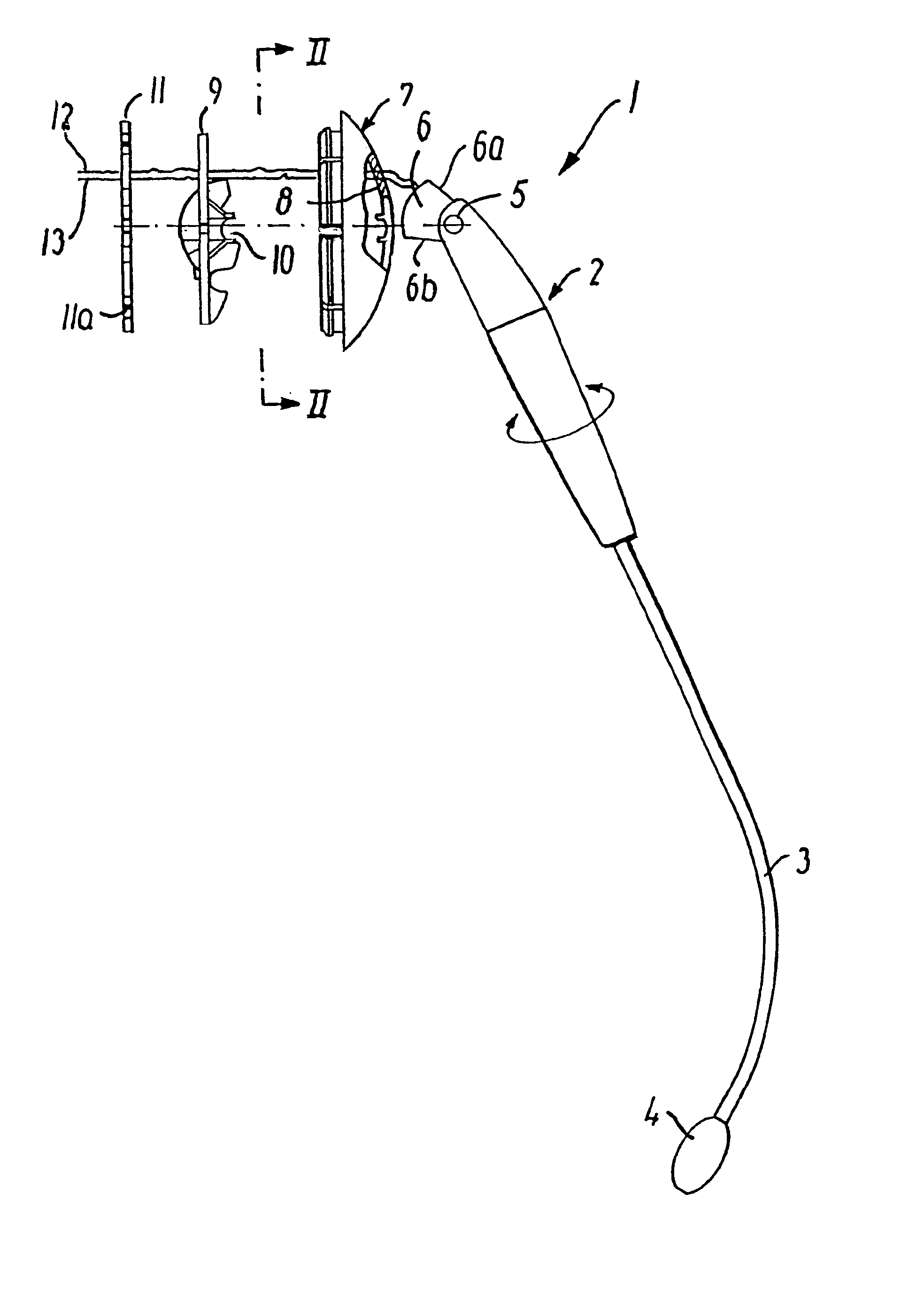
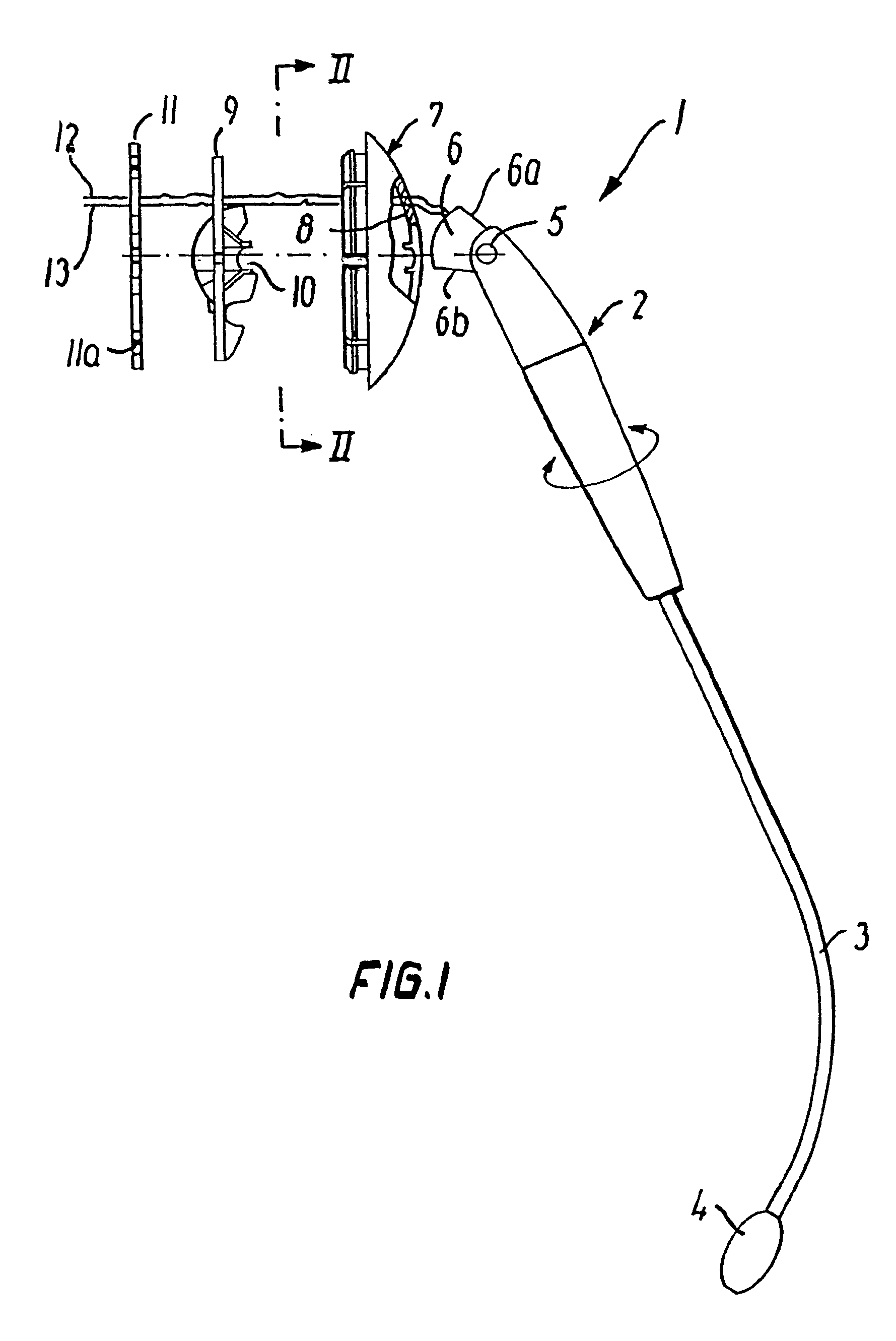
[0024]In FIG. 1, a microphone boom in its entirety is indicated by the reference number 1. As will be seen, at its one end it consists of a microphone 4 which is secured to the one end of a boom 3, while the other end of the boom 3 is connected to a pivotal adjusting piece 2. The adjusting piece 2 ends at a friction part 6 which has two opposing surfaces 6a and 6b. The friction part 6 is pivotally connected to the adjusting part 2 by means of a shaft 5 which extends through the adjusting piece 2 and the friction part 6. This shaft 5 extends out through both sides of the adjusting part 2.

[0025]FIG. 1 also shows a housing 7 which is arranged to receive the friction part 6 and a plate 9 with bearing 10, as explained in more detail in the following.

[0026]Finally, FIG. 1 shows a locking ring 11 which is arranged to hold the plate 9 firmly in the housing 7.

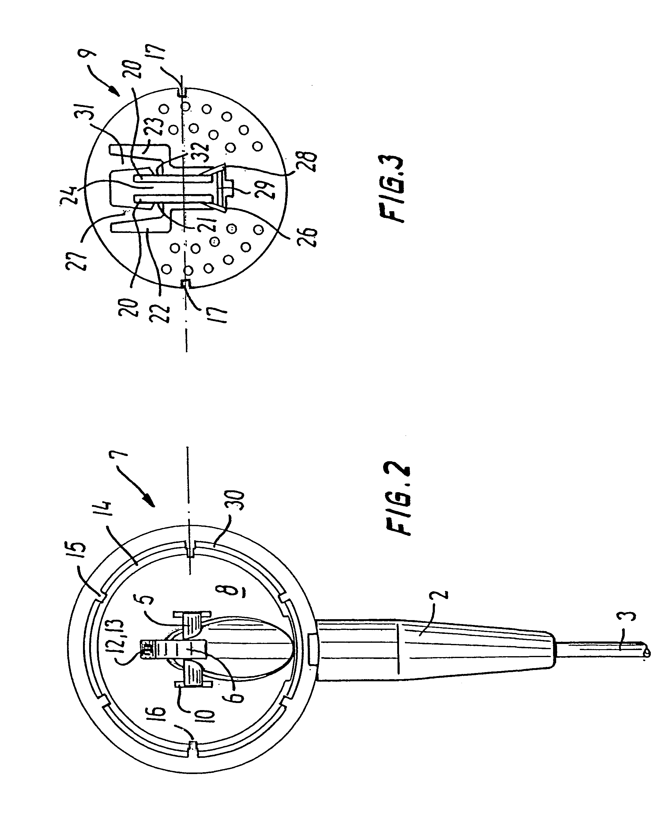
[0027]In FIG. 2, the housing is shown again seen in the direction II—II and with the friction part 6 inserted in the housing. As will ...


PUM


Abstract

A headset with an adjustable microphone boom which can be adjusted to and from a position near the mouth of a user and is mounted in a housing by a friction part being coupled to a flexible friction coupling which is configured in a plate in that co-operating plates are stamped out of the plate and are connected to the plate by means of flexible arms. The friction part has a shaft which can be accommodated in a bearing defined by recesses which are configured partly in the inside of the housing and partly in the plate. The microphone boom, the housing and the plate with friction coupling are held together by means of a locking ring. In this way a stable, adjustable microphone boom is provided which does not become loose with time, understood in the way that no matter in which position and regardless of how frequently the position is changed, the microphone boom will remain secured with a sufficient force in the friction coupling.

Description

TITLE OF THE INVENTION[0001]1. Techincal Field[0002]The invention concerns a headset with an adjustable microphone boom, which is swingable to or from a user's cheek, where the boom is mounted in a bearing provided in a housing, the microphone boom being suspended in the housing by a friction part configured on the microphone boom.[0003]2. Background[0004]Such headsets are to be found in increasingly widespread use, e.g. among personnel at reception desks and by personnel engaged in telephonic sales.[0005]Today, a modern headset is built up so that the user can wear it without any inconvenience arising in the form of discomfort due to the weight of the headset or its clamping around the head etc.[0006]Moreover, if the headset is of the wireless type, it is seldom necessary for the user to remove the headset from the head.[0007]In connection with periods during which the headset is not in use, it is desirable to be able to remove the microphone boom from the area around the mouth, e....

Claims


Application Information

Patent Timeline
Patent Type & Authority Patents(United States)
IPC IPC(8): H04R25/00H04M1/05H04R1/10
CPCH04M1/05H04R1/1058H04R1/08H04R2420/07H04R2201/107H04R1/10
Inventor BIRCH, OLE
Owner GN NETCOM
Why Eureka
Try Eureka