Control method for an exhaust gas purification system and an exhaust gas purification system

a technology of exhaust gas purification system and control method, which is applied in the direction of electrical control, exhaust treatment electric control, separation process, etc., can solve the problems of increasing exhaust gas pressure as a result of filter clogging, increasing the amount accelerating the accumulation of pm in the filter, so as to achieve the effect of efficiently regenerating and sufficient burnt pm collected in a dp

Inactive Publication Date: 2007-02-27
ISUZU MOTORS LTD
View PDF11 Cites 35 Cited by
  • Summary
  • Abstract
  • Description
  • Claims
  • Application Information

AI Technical Summary

Benefits of technology

[0014]It is an object of the present invention to provide a control method for an exhaust gas purification system and an exhaust gas purification system capable of sufficiently burning and removing the PM collected in a DPF and moreover efficiently regenerating the DPF when a forced regeneration is restarted after interruption in a DPF device.
[0021]Therefore, it is possible to sufficiently burn and remove the PM collected in a DPF. Moreover, in the case other than the above case, a forced regeneration is performed for the remained period of time of the previous forced regeneration control continuing to the previous forced regeneration. Thereby, the DPF can be efficiently regenerated.

Problems solved by technology

However, even in continuous regeneration DPF devices, increasing exhaust gas pressure as a result of filter clogging has become a problem.
Accordingly, the accumulation of PM in the filter continues and clogging thereof is accelerated.
Moreover, in the case of the prior art, the forced regeneration is interrupted when an engine key is turned off or a PTO (Power Take Off) is actuated.
However, when the forced regeneration is interrupted at the time of PTO actuation, there is a problem that PM is accumulated while it is interrupted and the collected PM cannot be sufficiently burned or removed by performing forced regeneration only for the remained period of time when restarting the next forced regeneration.
However, in the case where long distance is traveled by the next regeneration, PM is collected beyond expectation to cause a problem that the PM accumulated in a DPF cannot be sufficiently burned or removed by performing forced regeneration only for the remained period of time when restarting the next forced regeneration.
However, this exhaust particulate purification system has the following problem.
Therefore, the driver feels troublesome and moreover.
And the driver does not necessarily operate the cancel button.
Therefore, it is impossible to securely avoid a vehicle from being stopped during an automatic traveling regeneration.

Method used


Image

  • Control method for an exhaust gas purification system and an exhaust gas purification system
  • Control method for an exhaust gas purification system and an exhaust gas purification system
  • Control method for an exhaust gas purification system and an exhaust gas purification system

Examples


Embodiment Construction

[0028]Hereinafter, the preferred embodiments of the control method for an exhaust gas purification system and the exhaust gas purification system according to the present invention will be described with reference to the accompanying drawings. The following explanation will use the example of an exhaust gas purification system provided with a continuous regeneration-type DPF device comprising a combination of an oxidation catalyst and a filter with a catalyst.

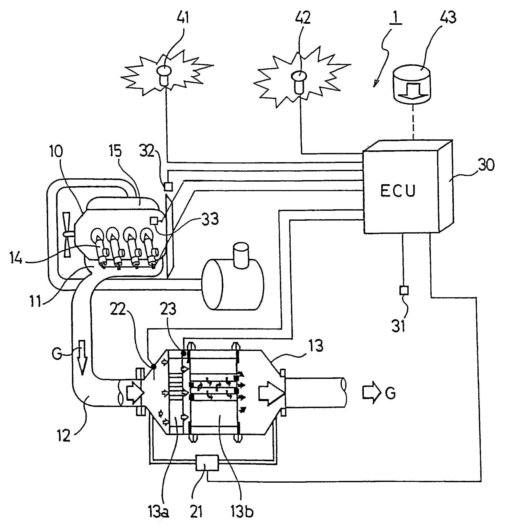
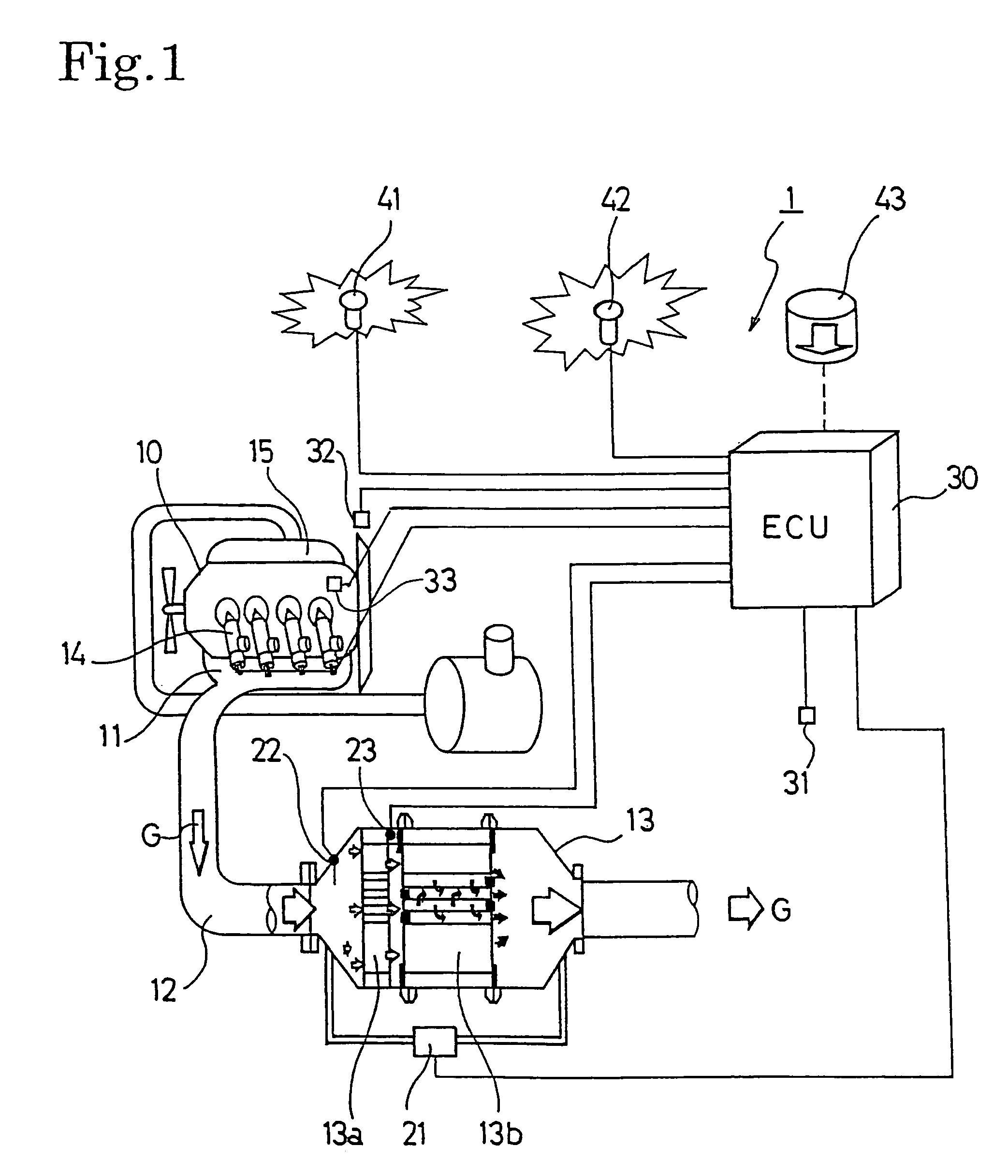
[0029]FIG. 1 shows the configuration of an exhaust gas purification system 1 for an internal combustion engine according to an embodiment of the present invention. This exhaust gas purification system 1 is configured to provide a continuous regeneration DPF (diesel particulate filter) device 13 on an exhaust passage 12 connected to an exhaust manifold 11 of a diesel engine 10. This continuous regeneration-type DPF device 13 is configured with an oxidation catalyst 13a on the upstream side thereof and a filter with catalyst 13b ...


PUM

PropertyMeasurementUnit
temperatureaaaaaaaaaa
travel distanceaaaaaaaaaa
exhaust gas temperatureaaaaaaaaaa

Abstract

When a forced regeneration is restarted after interrupting the forced regeneration, and in at least any one of cases where the collecting quantity area (Rpj) detected by the collecting quantity area detection means (32C) is in another collecting quantity area having a collecting quantity larger than that of the collecting quantity area (Rpi) immediately after interruption, or where the travel distance area (Rmj) detected by the travel distance area detection means (33C) is in another travel distance area, having a travel distance larger than that of the travel distance area (Rmi) immediately after interruption, the forced regeneration is performed from the start, and in other case, the forced regeneration is performed for the remained period of time of the previous forced regeneration, continuing to the previous forced regeneration.Thereby, in the case of an exhaust gas purification system (1), provided with a DPF device (13), when the forced regeneration for the DPF device (13) is restarted after interruption, it is possible to sufficiently burn and remove the PM accumulated in the DPF (13b) and moreover, efficiently regenerate the DPF (13b).

Description

BACKGROUND OF THE INVENTION[0001]The present invention relates to an exhaust gas purification system that purifies particulate matters from the exhaust gas discharged by diesel and other internal combustion engines using a diesel particulate filter and also to a control method thereof.[0002]In the same way as for NOx, CO, and also HC etc., restrictions on the volume of particulate matters (hereinafter “PM”) discharged from diesel internal combustion engines grow severe every year. Techniques for collecting this PM in a filter known as a diesel particulate filter (hereinafter “DPF”) and for reducing the quantity thereof by discharging externally have been developed. There is a continuous regeneration-type DPF device using DPF devices and a catalyst as one of them.[0003]However, even in continuous regeneration DPF devices, increasing exhaust gas pressure as a result of filter clogging has become a problem. Although the PM collected by the DPF is continuously burned and purified, and t...

Claims


Application Information

Patent Timeline
Patent Type & Authority Patents(United States)
IPC IPC(8): F01N3/00F01N3/02B01D46/42F01N3/023F01N3/025F01N3/18F01N3/24F01N9/00F01N11/00F02D41/02F02D41/40F02M25/07
CPCF01N3/0235F01N9/002F02D41/029F01N3/0231F01N3/0253F01N2430/08F01N2430/085Y02T10/47F02D41/402F02D41/405F02D2041/228F02D2200/0812F02M25/0718F02M25/0727F02M26/15F02M26/23Y02T10/40
Inventor SATO, HITOSHIHIRAKI, NOBUYUKIMASHIKO, TATSUO
Owner ISUZU MOTORS LTD
Why Eureka
Try Eureka