Carburetor

a carburetor and air technology, applied in the field of carburetor, can solve the problems of unstable inability to control air input well, and more pollution, so as to reduce pollution, improve performance, and stabilize the mixture of fuel and air

Inactive Publication Date: 2008-11-06
BORCH CORP
View PDF15 Cites 0 Cited by
  • Summary
  • Abstract
  • Description
  • Claims
  • Application Information

AI Technical Summary

Benefits of technology

[0008]An object of the present invention is to provide a carburetor, which controls a Venturi cone assembly using a cam to changes the design of a main oil passage so that a core can not only choke air, but also blocks fumes from the fuel. The present invention adopts a vacuum horsepower adjustment valve as an assistant oil passage, thereby making the mixture of fuel and air more stable, reducing pollution and improving performance.
[0010]The efficacy of the present invention is as follows: the cam of the present invention controls the shift of the cone of the Venturi cone assembly under vacuum suction from the engine to limit the position, to mix the air and fuel in a proper amount, and burns the entirety of the fuel. Furthermore, the exit for the main oil path is formed in front of the cone and has a fixed size so that the fuel and air are mixed more uniformly and the fuel can burn sufficiently. Additionally, the vacuum horsepower adjustment valve can automatically adjust the fuel supply at varied speeds to provide better horsepower and improve the efficacy of the carburetor.

Problems solved by technology

When the locomotive moves at high speeds, due to the cone design of the oil injection needle, a gap between the oil injection needle and an emulsifying pipe becomes larger following the movement of the oiling line so that the overflowed fuel particles is difficult to atomize and fuel cannot burn sufficiently, thereby causing more pollution.
Furthermore, when the choke cone runs under vacuum suction from the engine, the precise location of the choke cone cannot be controlled effectively, thereby the amount of air input cannot be controlled well and the mixture of the fuel and air is unstable.

Method used


Image

  • Carburetor
  • Carburetor
  • Carburetor

Examples


Embodiment Construction

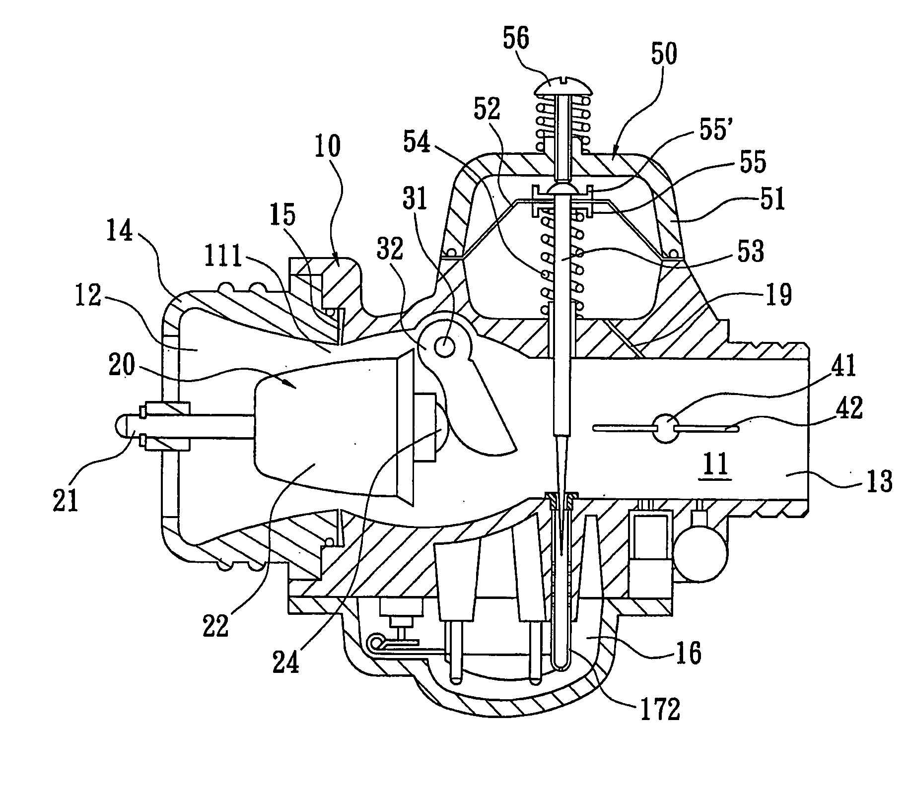
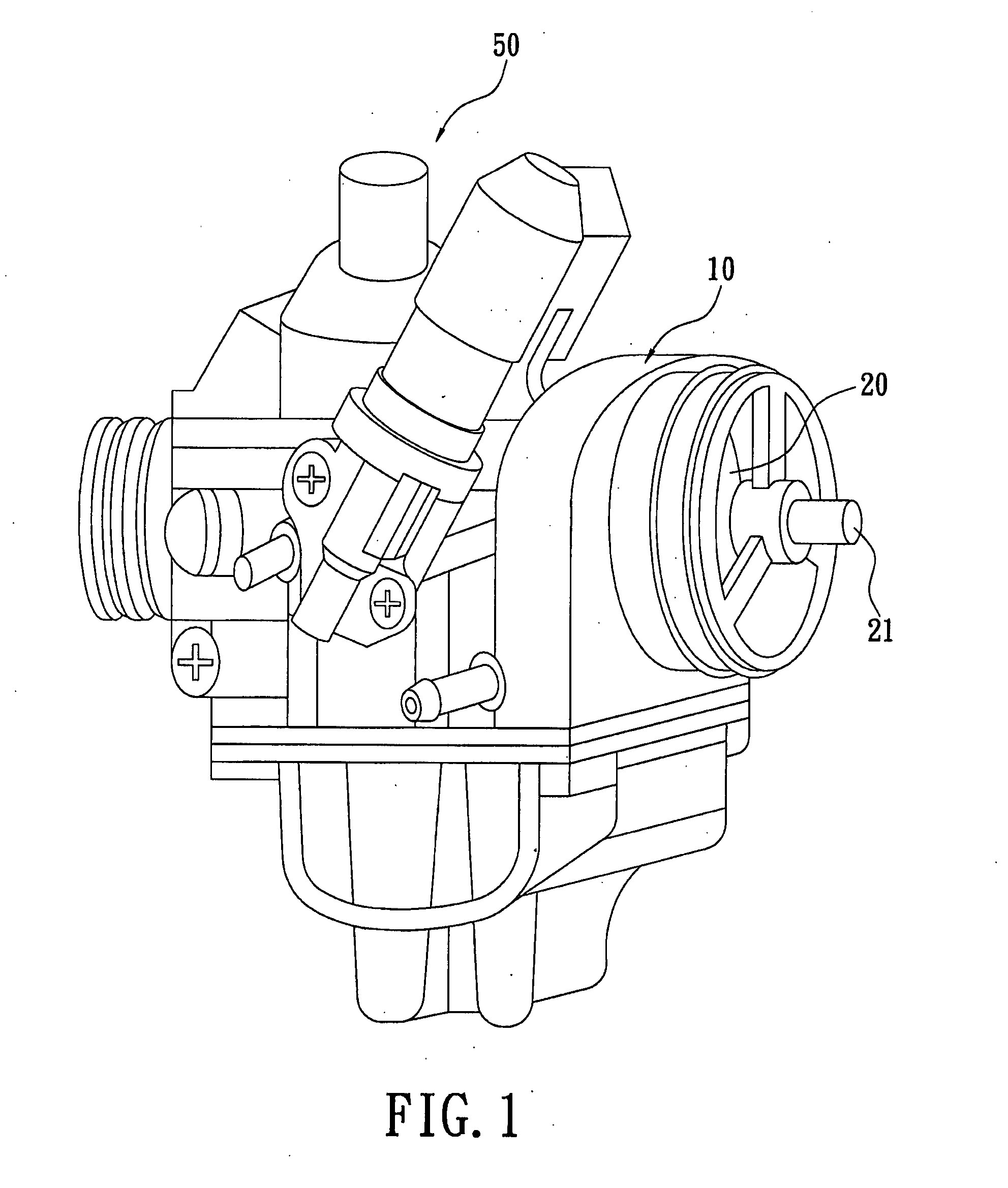
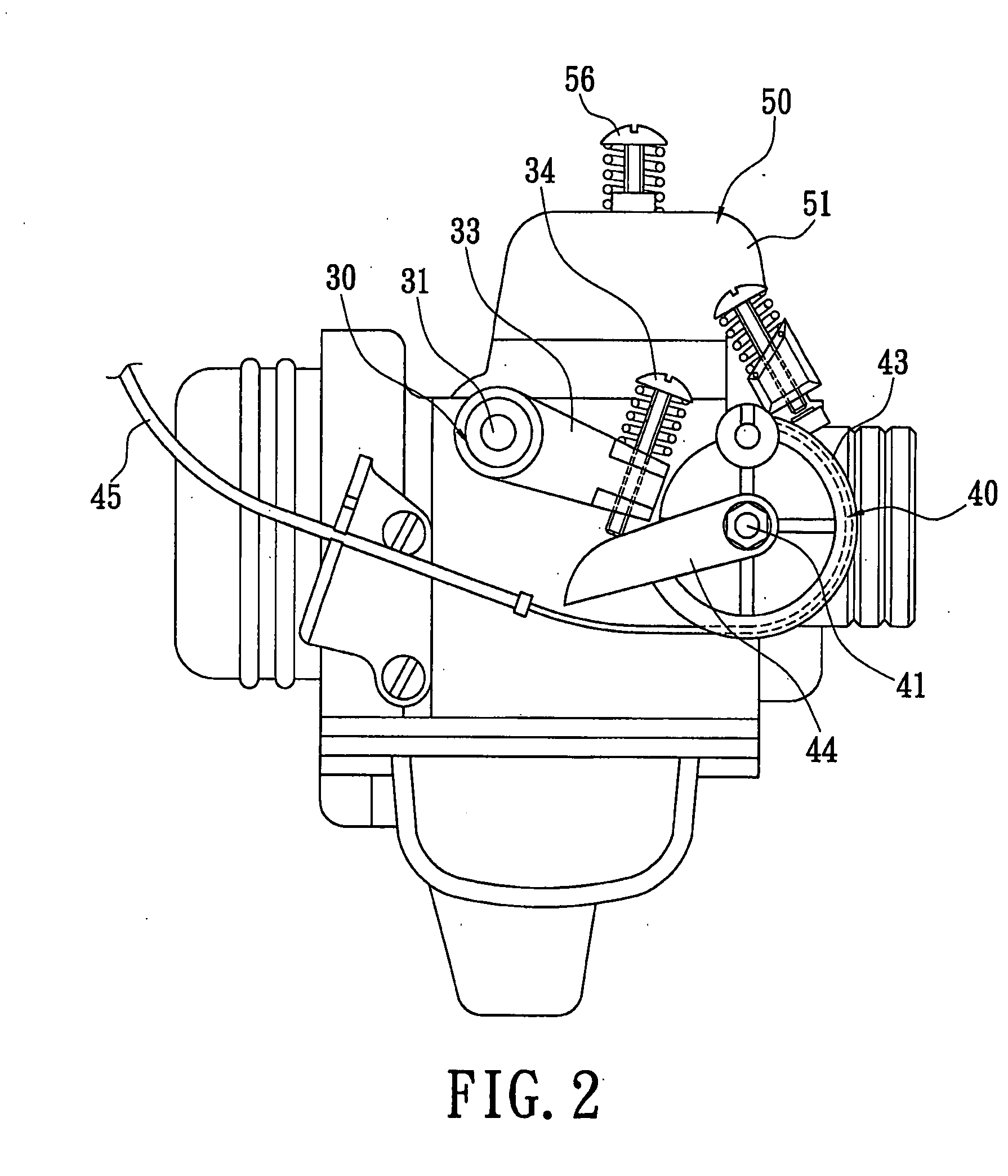
[0020]Please refer to FIGS. 1-3 in which a carburetor in accordance with a preferred embodiment of the present invention is shown. The carburetor includes a base 10, a Venturi cone assembly 20, a cam assembly 30, a horsepower adjustment assembly 40, and a vacuum horsepower adjustment valve 50.

[0021]The base 10 has a center flow path 11 through an inside thereof and forms an air inlet port 12 and an air outlet port 13 at opposite ends of the center flow path 11 respectively. A supporting portion 14 is mounted on the base 10 at the side of the air inlet port 11. An annular exit for the main oil path 15 is formed between the supporting portion 14 and the base 10. The base 10 has an oil groove 16, a plurality of emulsifying pipes 17 connecting with the oil groove 16 (please refer to FIG. 6) and two chunnels 18 connecting with the oil groove 16 and the exit for the main oil path 15 thereinside. The emulsifying pipes 17 include two emulsifying pipes for the main oil path 171 and an emulsi...


PUM

PropertyMeasurementUnit
speedaaaaaaaaaa
speedsaaaaaaaaaa
sizeaaaaaaaaaa

Abstract

A carburetor includes a base, a Venturi cone assembly, a cam assembly, a horsepower adjustment assembly, and a vacuum horsepower adjustment valve. The Venturi cone assembly is mounted in the base. A supporting portion of a cone collides with a cam of the cam assembly. An oil line rotation wheel of the horsepower adjustment assembly is drawn by an oiling line to drive the fan blade. The amount of displacement of the cone of the Venturi cone assembly under vacuum suction from the engine is controlled by a cam of the cam assembly. The vacuum horsepower adjustment valve automatically supplies enough fuel to the engine. Accordingly, the present invention can make the fuel burn sufficiently, effectively improving efficiency and reducing air pollution.

Description

BACKGROUND OF THE INVENTION[0001]1. Field of the Invention[0002]The present invention relates to a carburetor, and more especially to a carburetor for locomotives with a cam assembly and a vacuum horsepower adjustment valve, which is more efficient, saves fuel and reduces pollution.[0003]2. Description of the Prior Art[0004]The design of carburetors is important to improving the performance of locomotives. When consumers purchase locomotives, besides the speed of the locomotive, fuel efficiency and environmental protection are important factors which need to be considered. So before locomotives sold out, most of them need to have their idle-speed oil passage adjusted to minimize the amount of gas (such as HC, NOx, CO etc.) for obtaining the optimal fuel saving point, thereby achieving a state in which gas exhaust reach their lowest and fuel use is minimized.[0005]Taiwan Patent No. 398577, published on Jul. 11, 2000, provides an automatically adjustable carburetor which reduces fuel ...

Claims


Application Information

Patent Timeline
Patent Type & Authority Applications(United States)
IPC IPC(8): F02M7/12
CPCF02M7/17F02M9/133Y10S261/68
Inventor WANG, MING-CHING
Owner BORCH CORP
Why Eureka
Try Eureka