
Combination refrigerating appliance and evaporators for same

a technology of refrigerating appliances and evaporators, which is applied in the field of refrigerating appliances, can solve the problems of high energy consumption, high operating time of the refrigerating machine of the refrigeration appliance, and to a lower temperature of the refrigeration compartment, so as to reduce the energy consumption of the refrigerating appliance and reduce the operating tim

Inactive Publication Date: 2007-02-27
BSH BOSCH & SIEMENS HAUSGERAETE GMBH
View PDF2 Cites 31 Cited by
  • Summary
  • Abstract
  • Description
  • Claims
  • Application Information

AI Technical Summary

Benefits of technology

[0005]The object of the invention is to define a refrigerating appliance and evaporators for a refrigerating appliance which enables a reduction of the operating time in the third operating mode and thereby prevent super-cooling the refrigeration compartment and reduce the energy consumption of the refrigerating appliance.
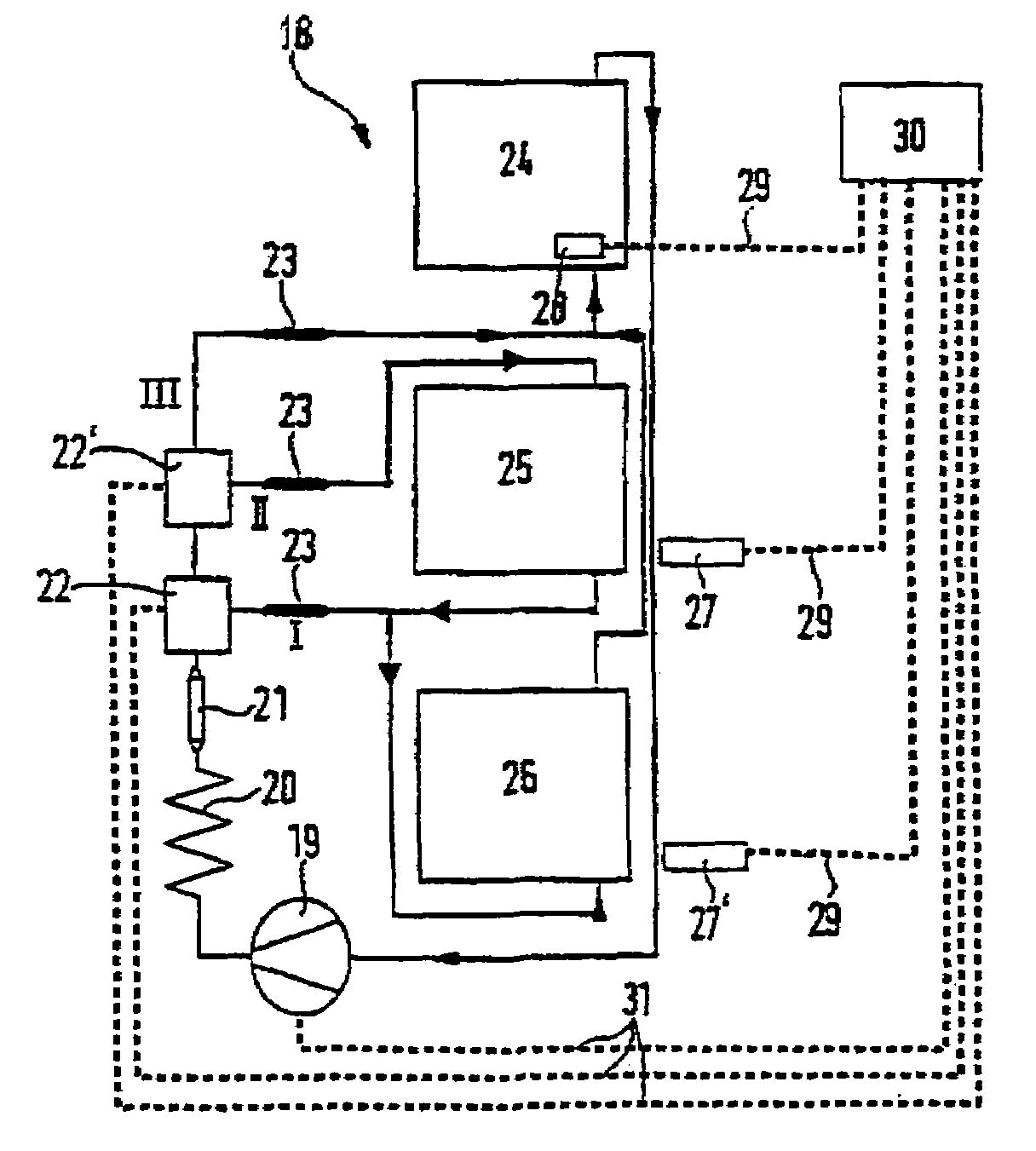
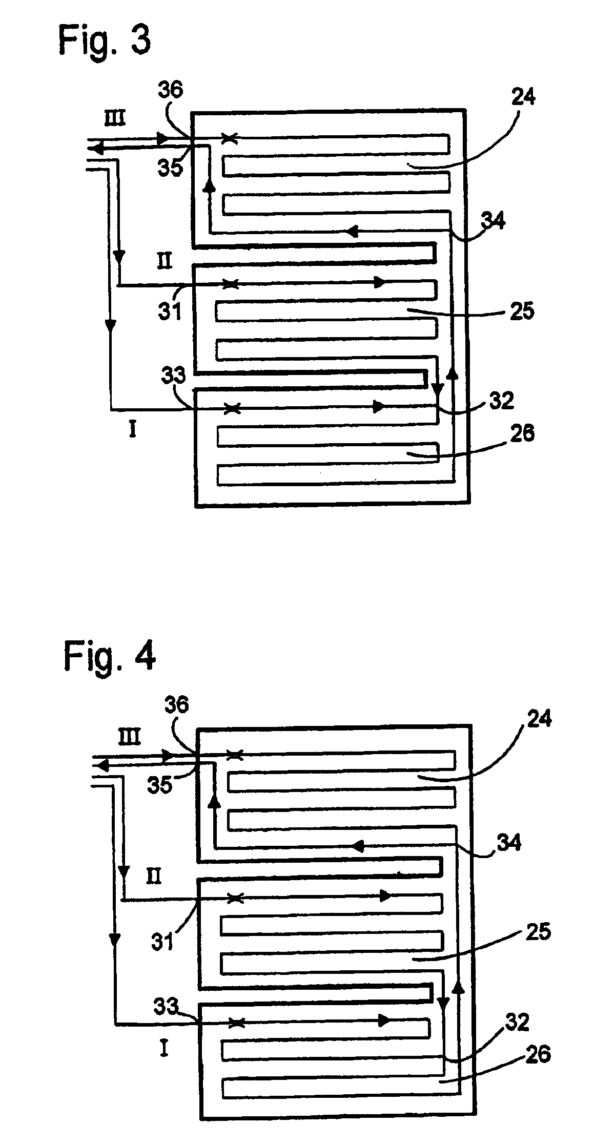
[0006]By connecting the evaporators of all three refrigerating areas sequentially in the second branch of the refrigerant circuit of the refrigerating appliance or by placing the connections on the evaporators so that a series connection of the three evaporators spans between two of the connections will be achieved that the third refrigerating area, the freezer compartment, will also be cooled when the refrigerant flow is routed over the second refrigerating area, the standard refrigeration compartment. The freezer compartment is therefore also continuously cooled when cooling the standard refrigeration compartment, so that the operating time required to adhere to the holding temperature of the freezer compartment is reduced in the third operating mode and therefore also the overall cooling period of the refrigeration compartment.

Problems solved by technology

This leads to a high overall operating time of the refrigerating machine of the refrigeration appliance and therefore to a high-energy consumption and to a lower temperature of the refrigeration compartments than necessary.

Method used


Image

  • Combination refrigerating appliance and evaporators for same
  • Combination refrigerating appliance and evaporators for same
  • Combination refrigerating appliance and evaporators for same

Examples


Embodiment Construction

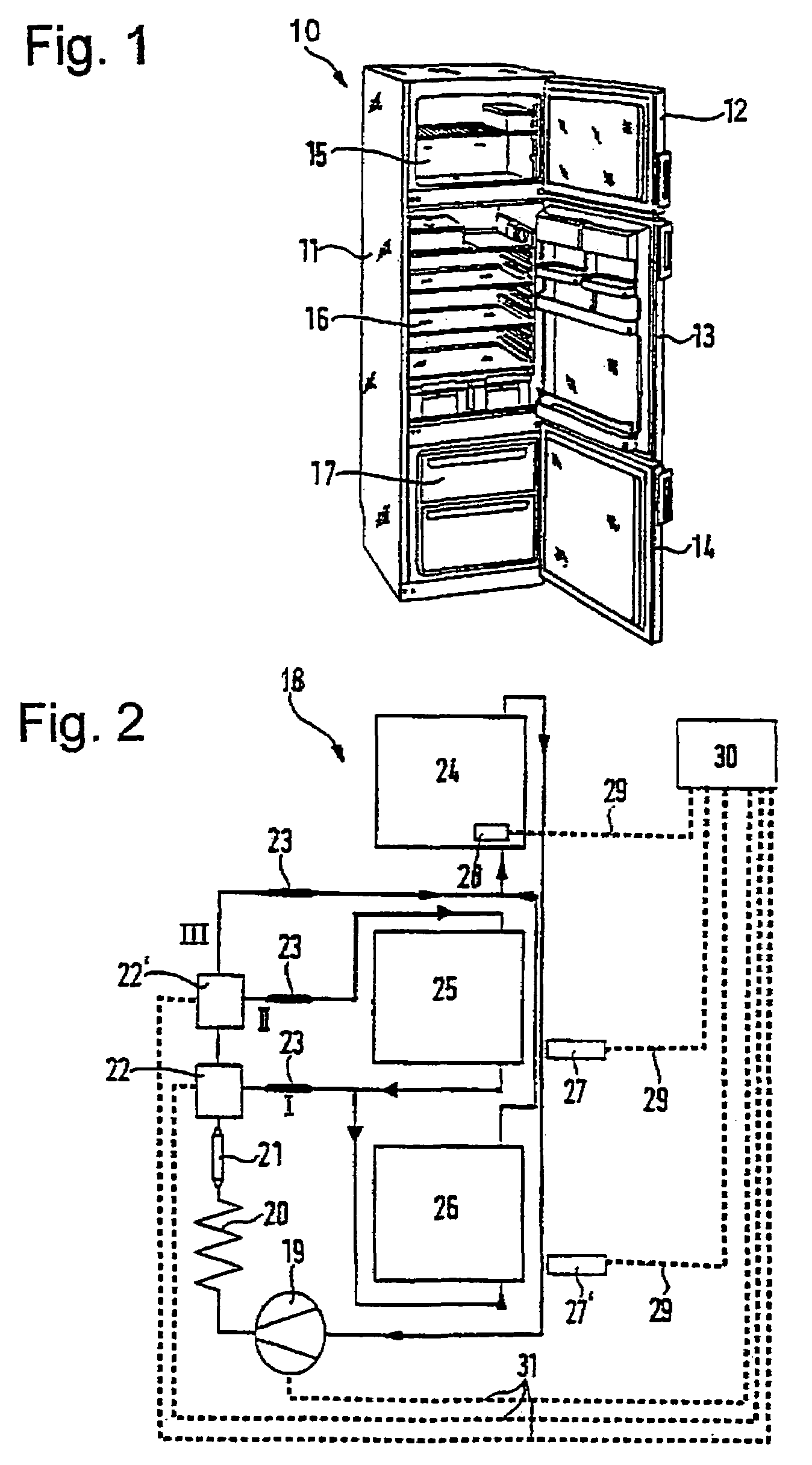
[0015]FIG. 1 shows a perspective of a household refrigeration appliance 10, whereof the heat-insulated housing 11 is provided with attached and doors 12–14 which open separately at its opening at the edge of the opening edge. Three compartments, which are superimposed and thermally separated by partitions in the interior of the housing 11, are lockable by the doors 12–14 which form the refrigerating areas 15–17 for various storage temperatures. The upper refrigerating area which may be locked by door 12 represents a refrigeration compartment, centre section 16, which is assigned to the door 13, serves as standard refrigeration compartment, while the section 17 located below is designed as freezer compartment and can be locked with the door 14. The various storage temperatures in the individual sections are maintained with the assistance of the refrigeration system described in the following.

[0016]The refrigeration system 18 illustrated schematically in FIG. 1 has a refrigerant compr...


PUM


Abstract

The refrigerating appliance comprises at least one first, second and third refrigerating area for a low, medium or high storage temperature, whereby each refrigerating area has an evaporator (24, 25, 26). The refrigerating appliance also comprises a compressor (19), a refrigerant circuit for supplying compressed refrigerant to the evaporators (24, 25, 26) and for returning expanded refrigerant to the compressor (19), and comprises at least one switching element (22, 22′) for directing, as desired, the refrigerant through one of two branches (I, II) of the refrigerant circuit. In the first branch (I), the evaporators (24, 26) of the first and the third refrigerating areas are connected in series. In the second branch (II), The evaporators (24, 25, 26) of all three refrigerating areas are connected in series.

Description

TITLE OF THE INVENTION[0001]The present invention relates to a refrigerating appliance with at least three refrigerating areas and evaporators for such a refrigerating appliance.[0002](2) Description of Related Art[0003]Such a refrigerating appliance is disclosed in DE 4 242 776 A1.[0004]This known refrigerating appliance has two valve units located in the refrigerant circuit and may be activated, in order to channel a refrigerant flow only through an evaporator dedicated to the first refrigerating area called a refrigeration compartment, or subsequently through an evaporator dedicated to the second refrigerating area described as standard refrigeration compartment and the refrigeration compartment evaporator or through a third evaporator dedicated to a refrigerating area described as freezer compartment and the refrigeration compartment evaporator. This means that the refrigerating appliance has three operating modes, a first in which only the refrigeration compartment is cooled, a...

Claims


Application Information

Patent Timeline
IPC IPC(8): F25B41/00F25B39/02F25B5/00F25D11/02
CPCF25B5/00F25D11/022F25B2600/02F25B2600/2511Y02B40/32F25D2400/04F25D2700/10F25D2700/12Y02B40/00
Inventor NUIDING, WOLFGANG
Owner BSH BOSCH & SIEMENS HAUSGERAETE GMBH
Learn More