Precipitation collecting gauge

Inactive Publication Date: 2007-02-27
HILL DAVID E
View PDF18 Cites 8 Cited by
  • Summary
  • Abstract
  • Description
  • Claims
  • Application Information

AI Technical Summary

Benefits of technology

[0009]The precipitation collecting gauge of the present invention thus includes a clear cylindrical elongated outer cylinder closed at its bottom and open at its top with an opaque or translucent elongated inner member disposed longitudinally in the clear cylindrical outer cylinder. A water receiver is defined in the space between the inner surface of the clear cylindrical outer cylinder and the o

Problems solved by technology

Unfortunately, it is difficult to make out the top surface of the water collected in such precipitation collecting gauges since typically the demarcation at the top surface of the water is not a sharp, well-defined one and low amounts

Method used


Image

  • Precipitation collecting gauge
  • Precipitation collecting gauge
  • Precipitation collecting gauge

Examples


Embodiment Construction

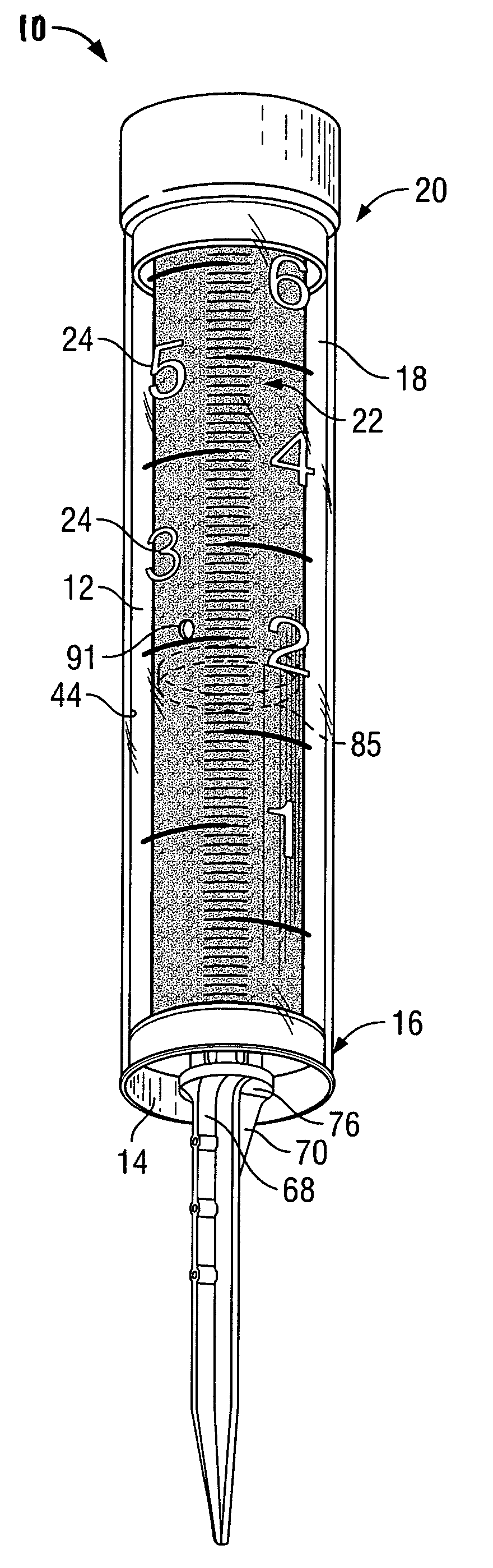
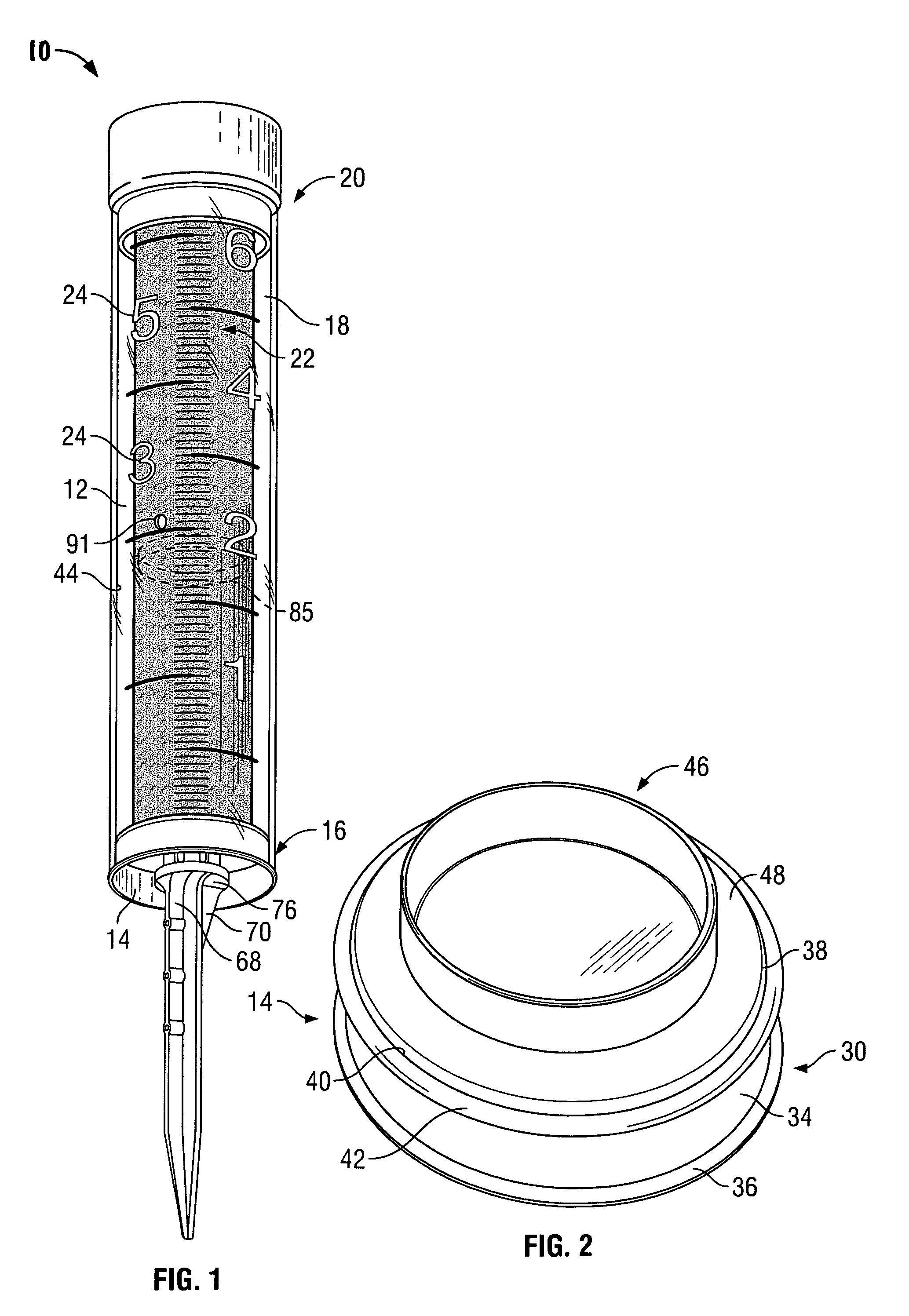
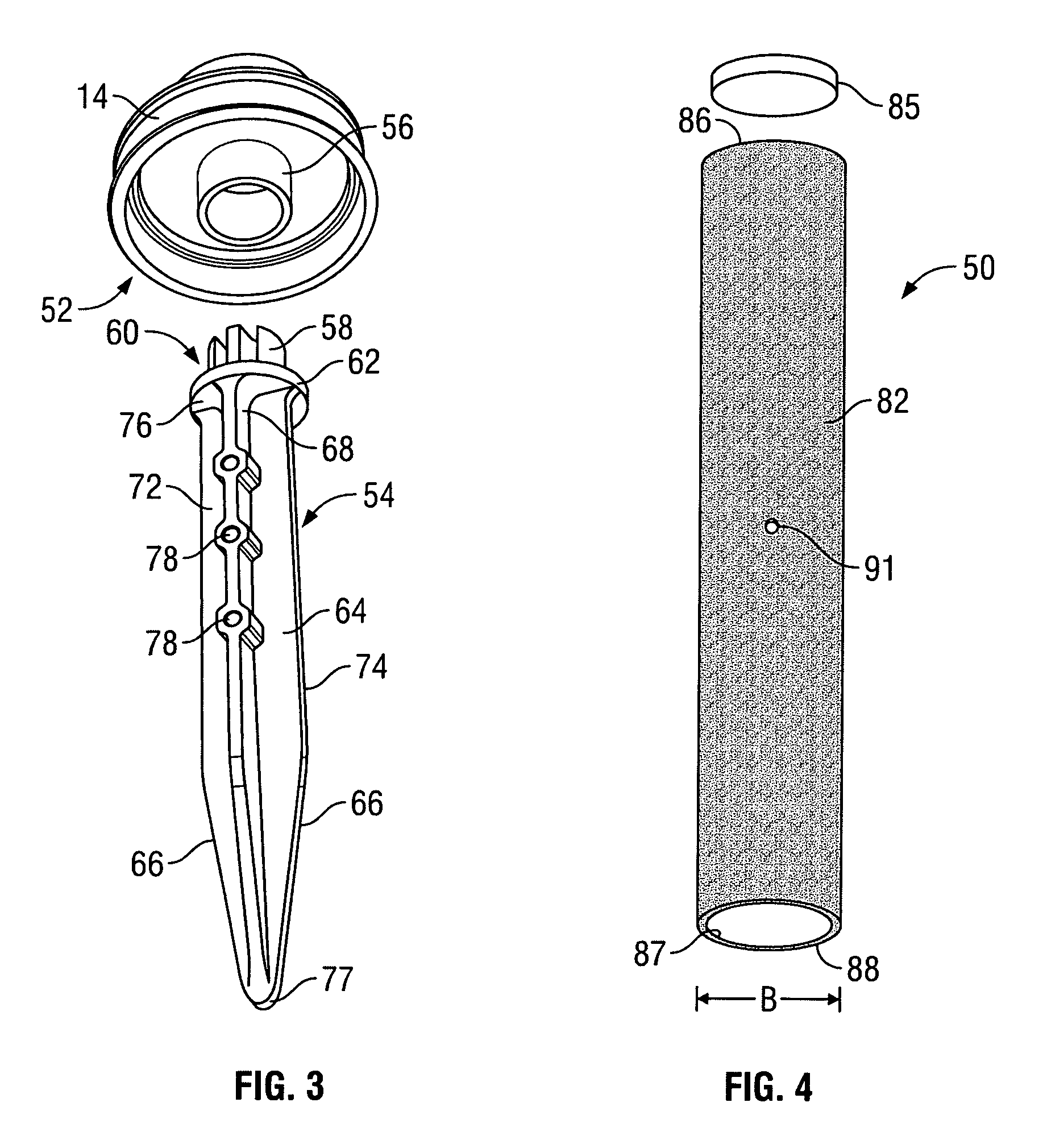
[0017]Turning now to FIG. 1, a precipitation collecting gauge 10 in accordance with the present invention is shown, including an elongated outer cylinder 12 having a bottom cap 14 which is sealingly fit within the bottom 16 of the cylinder. Although less preferred, outer cylinder may be made with a polygonal rather than a circular cross-section. Bottom-capped cylinder 12 thus comprises the water receptacle 18 of the invention. Although water receptacle 18 comprises two parts in the illustrated embodiment, the water receptacle may, of course, be of a unitary or one-piece construction. For example, water receptacle 18 may be molded from a single piece of an appropriate plastic.

[0018]Outer cylinder 12 is preferably clear about its entire periphery, as shown in FIG. 1. Although outer cylinder 12 may be made of any appropriate material, it is noted that one preferred material for the cylinder is PETG (glycolised polyester).

[0019]Cylinder 16 bears water level indicators in the form of a s...


PUM


Abstract

A precipitation gauge including a clear elongated outer cylinder and an opaque or translucent inner member disposed longitudinally in the outer cylinder to define a tubular water receiver in the space between the cylinder and the inner member and markings disposed along either the outer cylinder or the inner member, the gauge indicating the amount of water collected in the water receiver with a sharp demarcation at the top surface of the water resulting from an optical illusion making it appear that the portion of the gauge below the demarcation is filled with a fluid of the color of the inner member.

Description

BACKGROUND OF THE INVENTION[0001]This invention relates to devices for collecting and measuring precipitation and, more particularly, to a precipitation gauge for collecting precipitation including rain and sprinkler-deposited water and providing a visually well-defined water level demarcation at the top surface of the water collected in the gauge and an expanded measuring scale at low precipitation levels.[0002]Various types of devices are available for measuring precipitation. These devices typically collect the precipitation in a receptacle which has markings to indicate the level of water in the receptacle and hence the amount of precipitation collected over a period of time. Many of these prior art devices comprise containers with either a portion or the entirety of their vertical surfaces clear, so that the water within the container can be seen from a distance. Typically, level indications are applied either directly to clear areas on a container's outer surface or to areas i...

Claims


Application Information

Patent Timeline
IPC IPC(8): A63B53/00
CPCG01W1/14
Inventor HILL, DAVID E.
Owner HILL DAVID E
Why Eureka
Try Eureka