Unlock instant, AI-driven research and patent intelligence for your innovation.
Concrete curbing forming device
What is Al technical title?
Al technical title is built by PatSnap Al team. It summarizes the technical point description of the patent document.
a technology of curbing and forming device, which is applied in the direction of shaping building parts, forms/shuttering/falseworks, ways, etc., can solve the problems of limited life and considerable manual labor of the conventional method of preparing footings, and achieve the effect of reducing the spa
Inactive Publication Date: 2007-02-27
OLSEN BRET R
View PDF33 Cites 18 Cited by
Summary
Abstract
Description
Claims
Application Information
AI Technical Summary
This helps you quickly interpret patents by identifying the three key elements:
Problems solved by technology
Method used
Benefits of technology
Benefits of technology
[0014]A primary object of the invention is to reduce labor when constructing a curb or footing structure. It is apparent that the conventional technique of preparing footings consumes considerable manual labor to drive in wood stakes, that have the propensity to split and crack, and have limited life due to the nailing requirements, as well as hand nailing the cross ties having the same limitations. The present invention clearly reduces labor as the cleat is unitary and replaces the stakes while automatically spacing the two footing boards apart at a predetermined distance. The spacer boards are oppositely positioned against flanges on the cleat and a spreader is placed between the boards to hold the boards apart. The spreader is removed when the concrete is poured to the proper level thereafter holding the boards in position until pouring is completed.
[0016]Another object of the invention utilizes spreaders that are easily removed during the pouring process and then carrying out the pour to the top thereby completely eliminating the requirement for downwardly depending arm members that hold the top inside of the board, as noted in certain prior art that has been previously developed and patented to accomplish the same task.
[0020]A final object of the invention is the ease of removal from the ground as it may be pulled upwardly by hand due to its thin and flat configuration. Storage is also easily accomplished as the cleat device is small and may nest together consuming a minimum of space.
Problems solved by technology
It is apparent that the conventional technique of preparing footings consumes considerable manual labor to drive in wood stakes, that have the propensity to split and crack, and have limited life due to the nailing requirements, as well as hand nailing the cross ties having the same limitations.
Method used
Image
Click on the blue label to locate the original text in one second.
Reading with bidirectional positioning of images and text.
Examples
Embodiment Construction
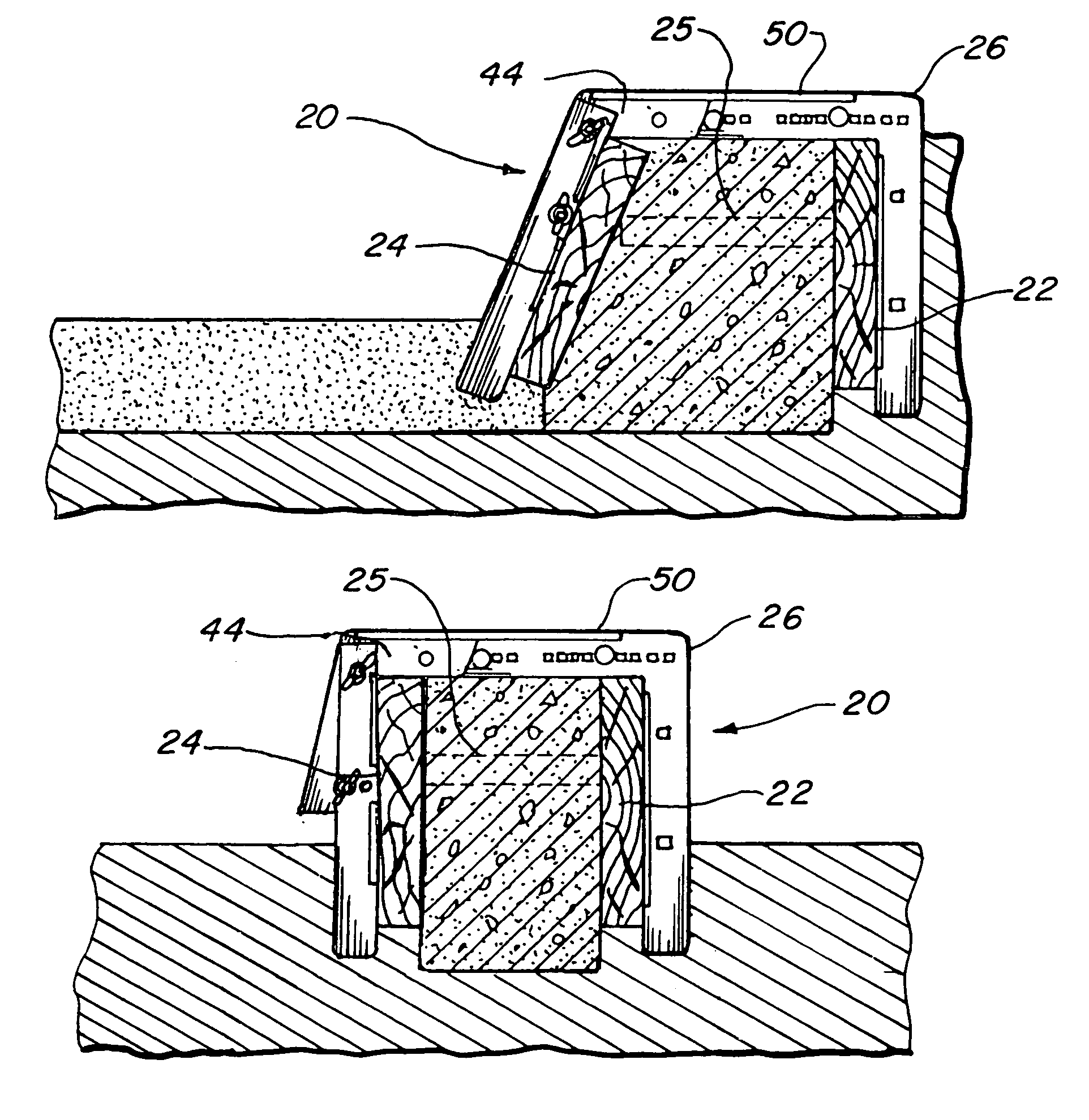
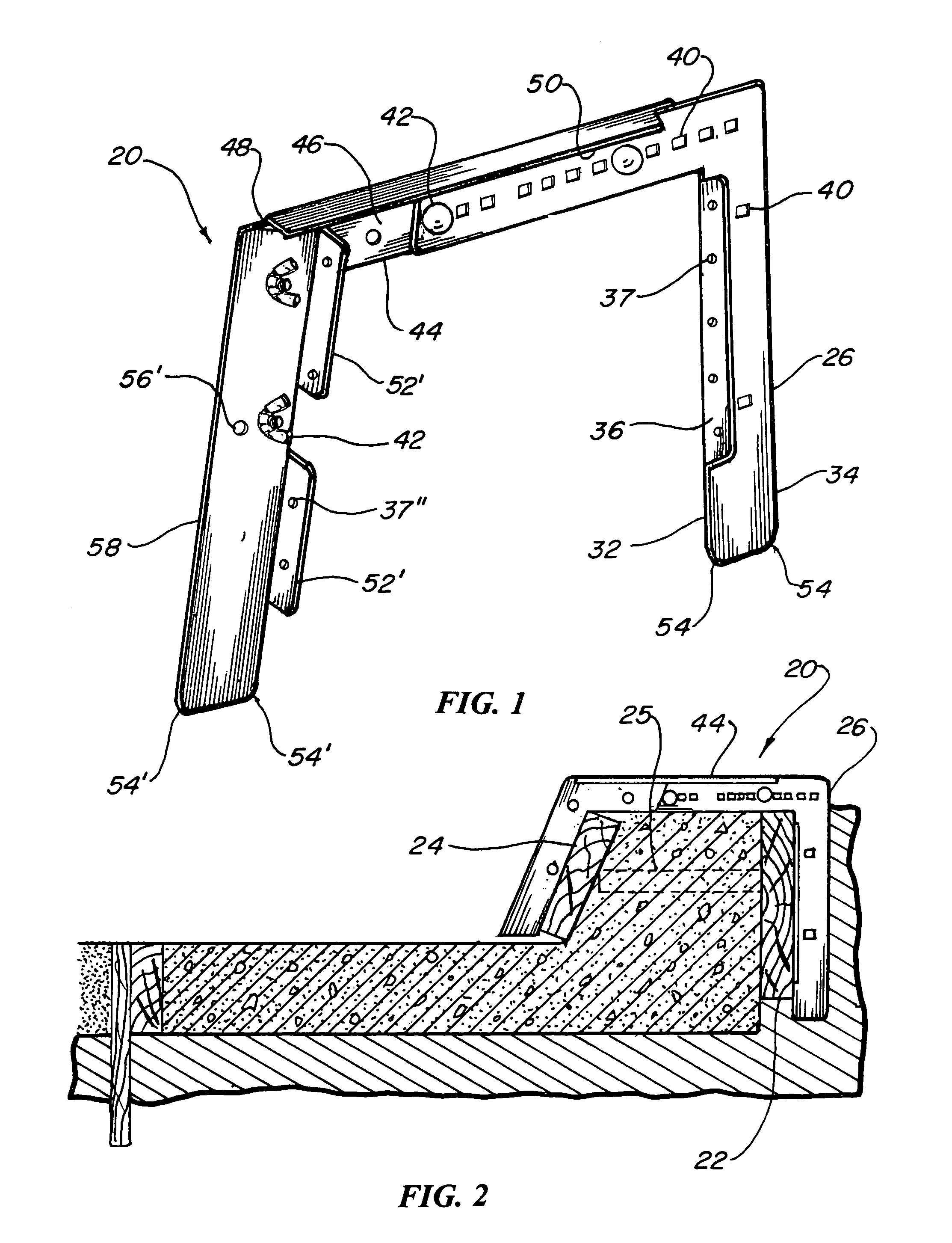
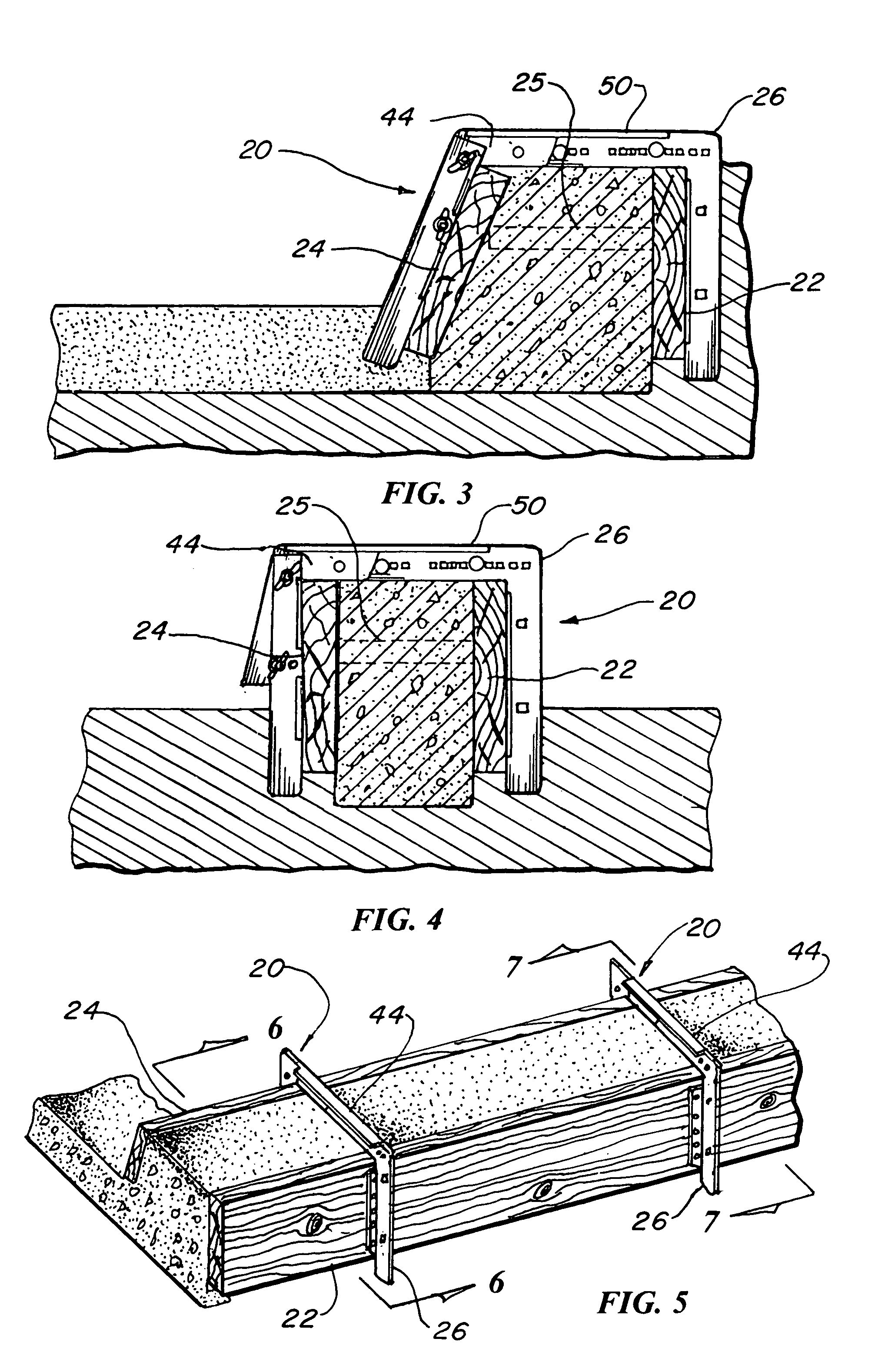
[0048]The best mode for carrying out the invention is presented in terms of a preferred embodiment and functions to provide forming to pour concrete curbing. This preferred embodiment of the cleat device 20 is shown in FIGS. 1 thorough 26 and is configured to jointly retain a wooden back board form 22 and a wooden front board form 24 with a spreader 25 spaced apart in-between.
[0049]The cleat device 20, illustrated assembled in FIG. 1, includes a right angle shaped cleat back 26, having an integral horizontal back top 28 and a integral downwardly depending back leg 30, configured to intimately engage and retain the back board form 22. The cleat back downwardly depending back leg 30 has an inner edge 32 and an outer edge 34 with a right angle flange 36 formed on the inner edge 32, as shown best in FIGS. 11–15. The right angle flange 36 includes a plurality of nail holes 37 for nailing the back board 22 in place eliminating the necessity of the spreader 25 or when required by the appli...
PUM
Abstract
A cleat device (20) is taught for forming concrete curbing that jointly retains a back board form (22) and a front board form (24) with a spreader (25) spaced apart between the forms. The cleat device consists of three basic elements first a right angle shaped cleat back (26) having a top (28) and leg (30) configured to intimately engage and retain the back board form. Second a cleat arm (44) that includes a top arm (46) and an acute angled downwardly depending member (48) attached to the cleat back top forming an inverted channel. The third element is a cleat leg (58) that is attached to the downwardly depending member allowing the cleat leg to be adjusted vertical or at an acute angle. Adjustment means provide a cleat device capable of supporting the back board and front board form with a spreader in-between while constructing a L-curb and gutter, a A-22 curb or a A-90 curb configuration.
Description
TECHNICAL FIELD[0001]The present invention relates to curb forming devices or cleats in general. More specifically to an adjustable cleat for forming so called concrete L-curbs, A-22 curbs and A-90 curbs.BACKGROUND ART[0002]Previously, many types of cleats, brackets, forms, clamps etc. have been used in endeavoring to provide an effective means to hold wood forms in place while pouring concrete into the form during the construction of a curb.[0003]A search of the prior art did not disclose any patents that possess the novelty of the instant invention; however the following U.S. patents are considered related:[0004]U.S. Pat. No.InventorIssue Date2,997,768TorrelliAug. 29, 19614,029,288Murphy et al.Jun. 14, 19774,291,858NeSmithSep. 29, 19814,494,725SimsJan. 22, 19855,048,781BreenSep. 17, 19915,562,272McAbbe et al.Oct. 8, 19966,409,422Mittermaier et al.Jun. 25, 2002[0005]Wilson in U.S. Pat. No. 2,956,950 teaches a curb form clamp for supporting the form boards during the pouring of conc...
Claims
Application Information
Patent Timeline
Application Date:The date an application was filed.
Publication Date:The date a patent or application was officially published.
First Publication Date:The earliest publication date of a patent with the same application number.
Issue Date:Publication date of the patent grant document.
PCT Entry Date:The Entry date of PCT National Phase.
Estimated Expiry Date:The statutory expiry date of a patent right according to the Patent Law, and it is the longest term of protection that the patent right can achieve without the termination of the patent right due to other reasons(Term extension factor has been taken into account ).
Invalid Date:Actual expiry date is based on effective date or publication date of legal transaction data of invalid patent.
