Safety device for a humidifier

a safety device and humidifier technology, applied in the direction of lighting and heating apparatus, heating types, separation processes, etc., can solve the problems of affecting the use of users, the water level remains in the water tank, and the disadvantage of the second conventional humidifier, so as to prevent improper sensing of water level

Inactive Publication Date: 2007-02-27
HUANG CHUAN PAN +1
View PDF15 Cites 17 Cited by
  • Summary
  • Abstract
  • Description
  • Claims
  • Application Information

AI Technical Summary

Benefits of technology

[0007]One purpose of the invention is to offer a safety device for a humidifier, making it possible to cut off the power immediately in case of the water level being lowered to a dangerous condition, and preventing improper sensing of the water level.
[0008]Another purpose is to offer a safety device for a humidifier possible to keep the lowest water level in a vaporizing chamber for quickly producing vapor.
[0012]3. The safety device has a film heater or an oscillator fixed in the bottom of the vaporizing chamber, with its vapor producing efficiency being high, not occupying much space and reducing partial dimensions of a humidifier.

Problems solved by technology

Its major disadvantage is that the sensor may give out a wrong signal in case of the water tank still having some water if the humidifier is inclined, and cannot cut off power in due time, causing danger to a user.
Then this second conventional humidifier has the same disadvantage as the first one.
This third conventional humidifier has a disadvantage that some water still remains in the water tank in case of the humidifier is inclined improperly, and a humidifier in the invention does not have this drawback.
One more conventional humidifier disclosed in a U.S. Pat. No. 4,563,313 has a float disposed in a water tank, having the same disadvantage as those described above.
Further, another disadvantage in those conventional humidifiers is too much water in the water tank, so it takes too long time for boiling by the heater for producing vapor.

Method used


Image

  • Safety device for a humidifier
  • Safety device for a humidifier
  • Safety device for a humidifier

Examples


Embodiment Construction

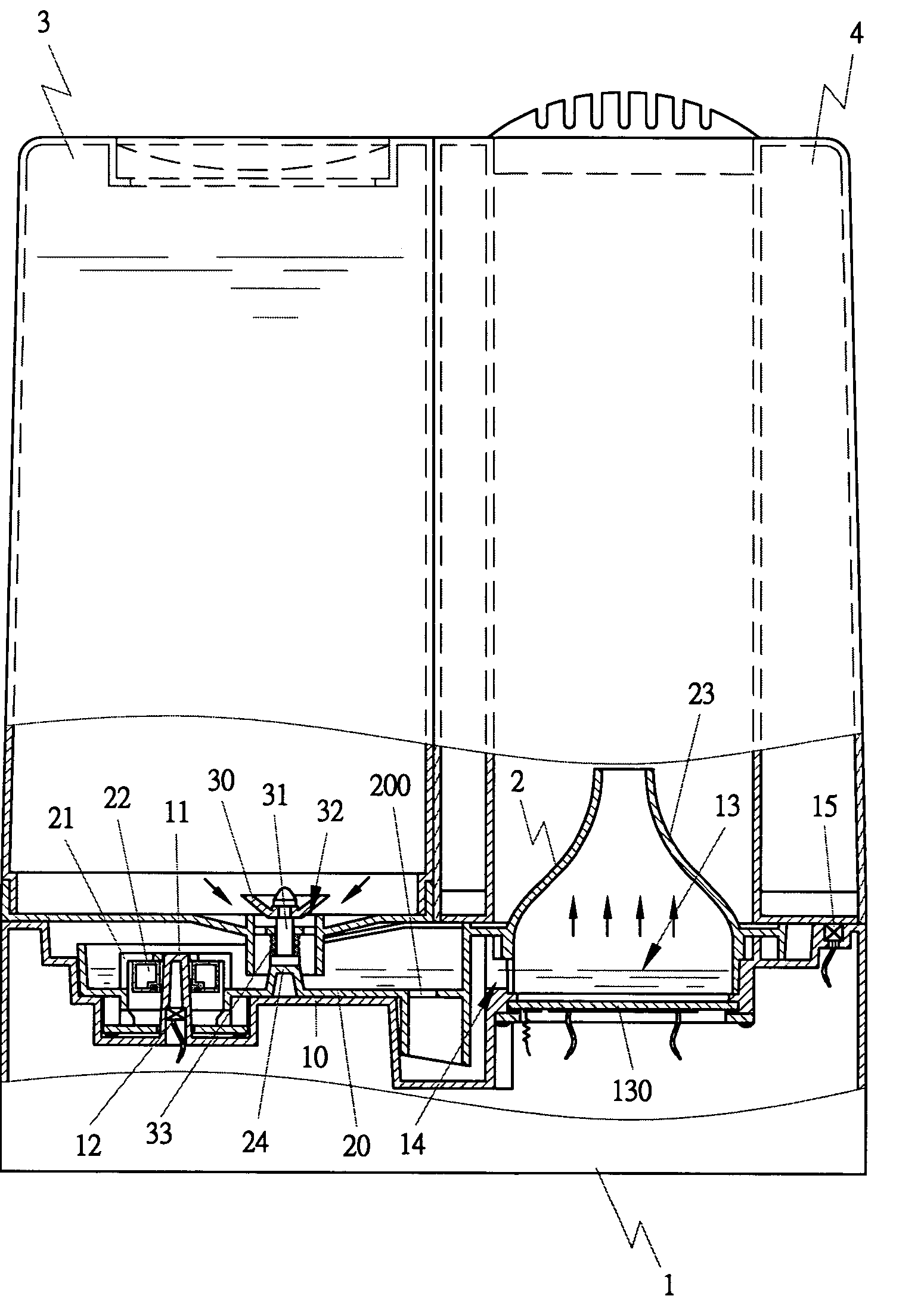
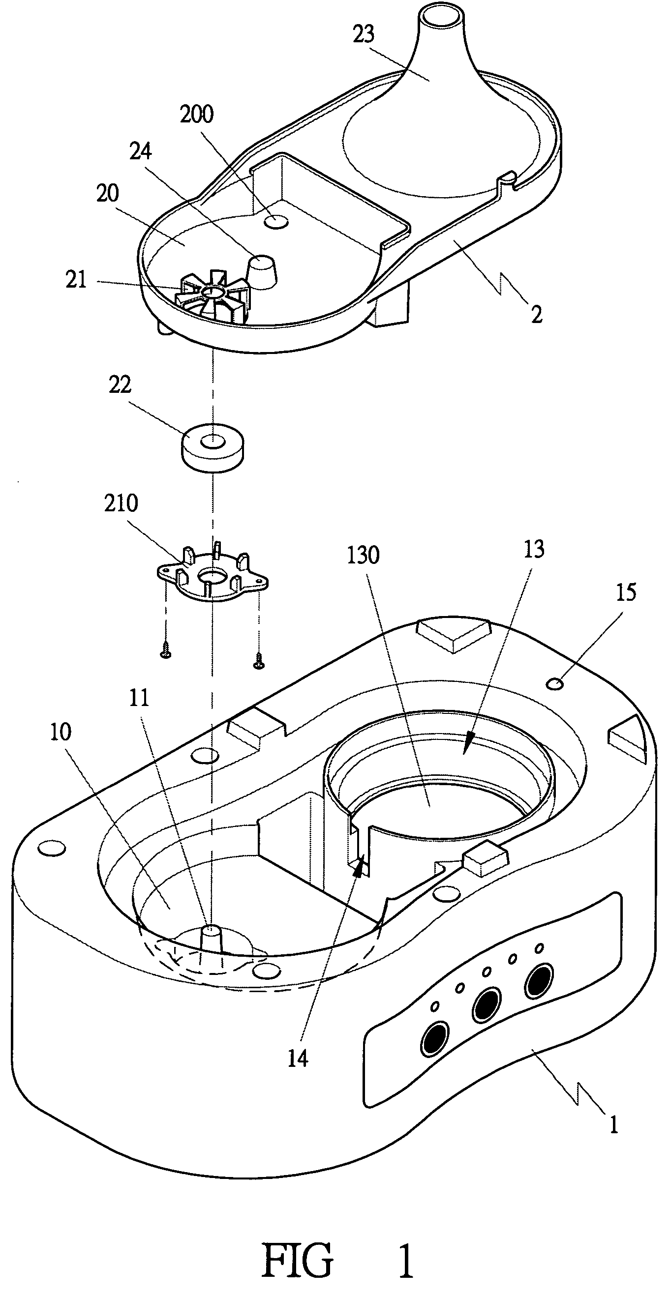
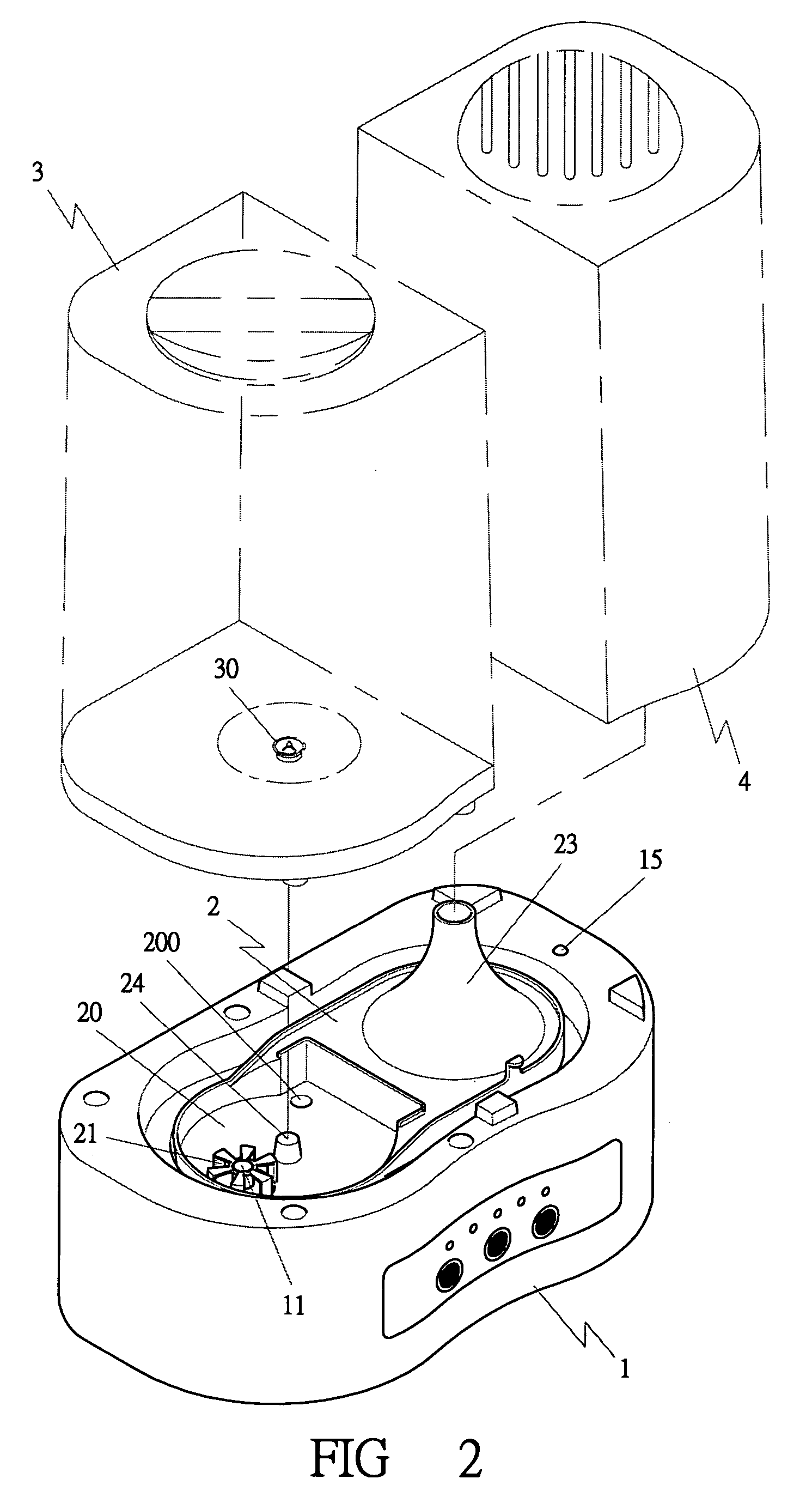
[0023]A first embodiment of a safety device for a humidifier in the present invention, as shown in FIGS. 1 and 2 includes a body 1, a sensor 12, a safety device 2, positioned on a water tank 3 and a vapor tank 4 of a humidifier.

[0024]The body 1 is provided with a water chamber 10 formed in one upper side, and a post standing in the center of the water chamber 10 and having a hollow interior, and a vaporizing chamber 13 formed in the other upper side and having a bottom 130 formed flat or a little inclined as shown in FIGS. 5 and 8 and a water passage 14 is provided between the water chamber 10 and the vaporizing chamber 13. Further, a vaporizer such as a thin film heater or an oscillator is deposited in the bottom 130.

[0025]Further, the safety device 2 is positioned on the water chamber 10 and the vaporizing chamber 13, and a safety sensor 15 is disposed properly around the vaporizing chamber 13, which can be an optical sensing member, or magnetic sensing member. When the vapor tank...


PUM

PropertyMeasurementUnit
boilingaaaaaaaaaa
poweraaaaaaaaaa
frequencyaaaaaaaaaa

Abstract

The present invention is directed to control method for supplying water in a humidifier. In a conventional humidifier, when the water level in the base of the humidifier is lowered to the ON / OFF critical region, with the vibration of the water level, the floating ball in the base will make ten's or hundred's times of ON / OFF vibrations, which tends to damage the high frequency vibration circuit. In addition, when the humidifier is inclined, the magnet on the floating ball remains in the attractive state with the magnetic spring switch that may cause fire of the electrical wires and leakage of the electricity. In the present invention, the floating ball is directly placed within a water tank, so that the magnetic spring switch can be effectively driven to conduct the ON / OFF movement, and the power can be cut off immediately when the water level of the water tank is lowered to the minimum level. When the humidifier is turned over by external force, the water tank will become separated from the base of the humidifier, which will break the contact between the floating ball and the magnetic spring switch so as to cut off the power, assuring the safety and extending the use time of the humidifier.

Description

FIELD OF THE INVENTION[0001]This invention relates to a safety device for a humidifier, particularly to one disposed between a body, a water tank, and a vapor tank and provided with a water level sensor, for sensing the water level in the water tank and cutting off power in due time, upgrading the safety of a humidifier.BACKGROUND OF THE INVENTION[0002]A conventional humidifier disclosed in a Taiwan patent No. 367023 is a first known one, which includes two sensors directly arranged in a water tank for checking the water level. Its major disadvantage is that the sensor may give out a wrong signal in case of the water tank still having some water if the humidifier is inclined, and cannot cut off power in due time, causing danger to a user.[0003]Another Taiwan patent No. 145330 disclosed a humidifier, a second known one that includes a water chamber in the bottom base, a magnetic switch fixed in the water chamber, a float provided in a water tank and having a magnet to correspond to t...

Claims


Application Information

Patent Timeline
Patent Type & Authority Patents(United States)
IPC IPC(8): B01F3/04
CPCF24F6/00F24F2011/0054F24F2006/008F24F2140/30
Inventor HUANG, CHUAN-PANHUANG, CHEN-LUNG
Owner HUANG CHUAN PAN
Why Eureka
Try Eureka