AI technical title is built by PatSnap AI team. It summarizes the technical point description of the patent document.
a reflective element and optical technology, applied in mirrors, instruments, vehicle components, etc., can solve the problems of difficult electrical contact between the semi-conductive and/or conductive layers of the substrate, and achieve the effect of improving the assembly process
Inactive Publication Date: 2007-02-27
DONNELLY CORP
View PDF128 Cites 568 Cited by
Summary
Abstract
Description
Claims
Application Information
AI Technical Summary
This helps you quickly interpret patents by identifying the three key elements:
Problems solved by technology
Method used
Benefits of technology
Benefits of technology
[0016]Therefore, the present invention provides an electro-optic or electrochromic cell or mirror reflective element assembly that provides an overhang region at at least one edge of the front substrate for electrical connection to the conductive layer at the rear surface of the substrate, such that the electrical connection is not viewable through the front surface of the front substrate. The present invention thus may provide a reflective element assembly that is suitable for use in a bezelless mirror assembly, where the front surface of the reflective element is substantially entirely viewable by a driver of the vehicle. Optionally, a reflective element assembly of the present invention may provide a flush alignment of an upper and / or lower edge of a pair of substrates, while providing clearance for electrical connection to the upper and / or lower edges of one of the substrates and the respective conductive coating. The present invention thus provides enhanced assembly processes for the mirror element, since the substrates may be aligned with one another within an assembly fixture and do not require stepped pins or spacers positioned along one edge to provide sufficient offset or staggering between the substrates to provide clearance for electrical connection to one of the substrates along the aligned or flush edge thereof.
Problems solved by technology
In cells or reflective element assemblies that may provide a small bezel or no bezel, it is often difficult to make electrical contact to the semi-conductive and / or conductive layers of the substrates with a restricted overhang between the substrates.
Method used
Image
Click on the blue label to locate the original text in one second.
Reading with bidirectional positioning of images and text.
Examples
Embodiment Construction
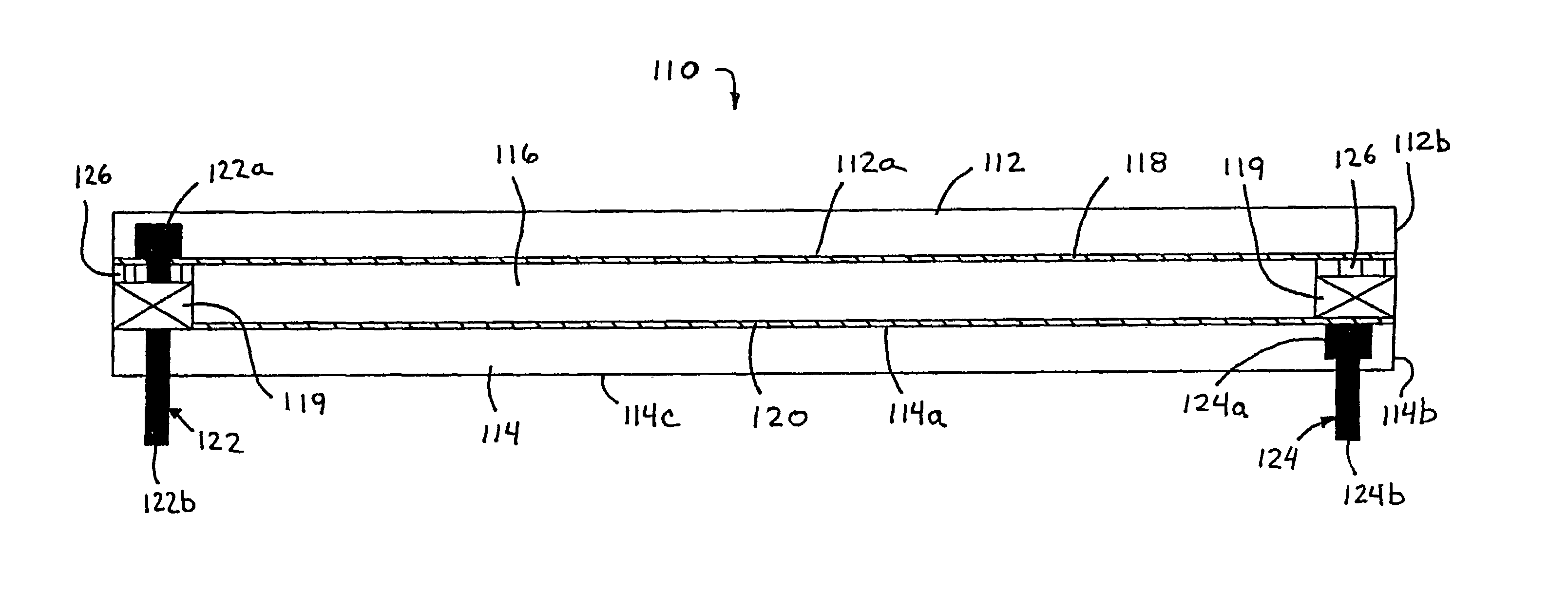
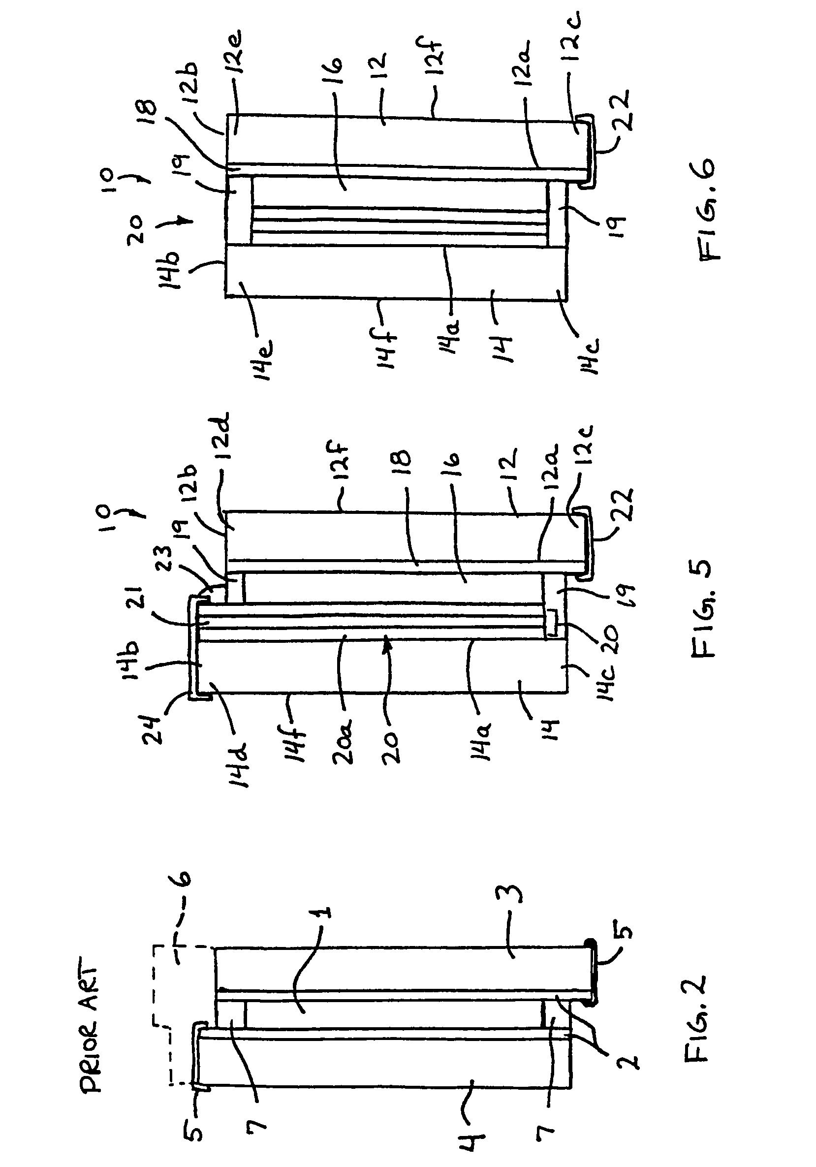
[0059]Referring now to the drawings and the illustrative embodiments depicted therein, an electro-optic or electrochromic cell or mirror element assembly or reflective element assembly 10 for an interior rearview mirror assembly of a vehicle (not shown) includes first and second glass substrates 12, 14 and an electro-optic or electrochromic medium 16 disposed or sandwiched therebetween (FIGS. 4–6). Electrochromic medium 16 and at least one metallic and / or non-metallic conductive or semi-conductive layers 18, 20 are disposed on the inner surfaces 12a, 14a of substrates 12, 14 and between the electrochromic medium 16 and the respective substrate 12, 14. At least one of the edges or sides 12b, 14b of the substrates 12, 14 are generally aligned with or flush with one another (as seen in FIGS. 4 and 6) at least along a portion of the edges. The reflective element or mirror element of the present invention is equally suitable for interior or exterior rearview mirror assemblies for vehicle...
PUM
Abstract
An electro-optic reflective element assembly includes a pair of substrates and an electro-optic medium sandwiched therebetween. Each of the pair of substrates includes at least one conductive or semi-conductive layer disposed thereon. The electrical connections may electrically connect to a respective layer and may be electrically isolated from the other layer, such as via non-conductive regions of the substrates and / or deletion lines along one of the conductive layers. The pair of substrates may be positioned relative to one another such that overhang portions of the front substrate extend beyond the corresponding edges of the rear substrate. The overlapping relationship may provide clearance for electrical connection to the conductive layers of the front and rear substrates such that the electrical connections are substantially not viewable through the front substrate.
Description
CROSS REFERENCE TO RELATED APPLICATIONS[0001]The present application is a 371 U.S. national phase application of PCT Application No. PCT / US2003 / 035381, filed Nov. 5, 2003, which claims priority of U.S. provisional applications, Ser. No. 60 / 490,111, filed Jul. 25, 2003 by McCabe et al. for FLUSH ELECTROCHROMIC CELL; and Ser. No. 60 / 423,903, filed Nov. 5, 2002 by McCabe for ONE SIDED FLUSH ELECTROCHROMIC CELL; and the present application is a continuation-in-part of U.S. patent application, Ser. No. 10 / 528,269, filed Mar. 17, 2005, which is a 371 application of PCT Application No. PCT / US2003 / 029776, filed Sep. 19, 2003, which claims priority of U.S. provisional applications, Ser. No. 60 / 412,275, filed Sep. 20, 2002 by McCabe for ELECTROCHROMIC MIRROR ASSEMBLY; Ser. No. 60 / 424,116, filed Nov. 5, 2002 by McCabe for ELECTROCHROMIC MIRROR ASSEMBLY; and Ser. No. 60 / 489,816, filed Jul. 24, 2003 by McCabe for ELECTROCHROMIC MIRROR ASSEMBLY, which are all hereby incorporated herein by referen...
Claims
Application Information
Patent Timeline
Application Date:The date an application was filed.
Publication Date:The date a patent or application was officially published.
First Publication Date:The earliest publication date of a patent with the same application number.
Issue Date:Publication date of the patent grant document.
PCT Entry Date:The Entry date of PCT National Phase.
Estimated Expiry Date:The statutory expiry date of a patent right according to the Patent Law, and it is the longest term of protection that the patent right can achieve without the termination of the patent right due to other reasons(Term extension factor has been taken into account ).
Invalid Date:Actual expiry date is based on effective date or publication date of legal transaction data of invalid patent.
Patent Type & AuthorityPatents(United States)
IPC IPC(8): G02F1/15
CPCB60R1/12G02F1/157B60R2001/1215
InventorMCCABE, IAN AVARAPRASAD, DESARAJUHABIBI, HAMIDLYNAM, NIALL R

