Magnetic disk loading apparatus

a technology of magnetic disks and loading apparatuses, which is applied in the direction of electric apparatus casings/cabinets/drawers, insulated conductors, instruments, etc., can solve the problems of ineffective utilization of vacant space inability to effectively utilize the vacant area, and small maximum number of magnetic disk units mounted in the magnetic disk loading apparatus. , to achieve the effect of easy shifting of cable positions

Active Publication Date: 2007-02-27
FUJITSU LTD
View PDF11 Cites 9 Cited by
  • Summary
  • Abstract
  • Description
  • Claims
  • Application Information

AI Technical Summary

Benefits of technology

[0011]Accordingly, an object of the present invention is to provide a magnetic disk loading apparatus accommodating a larger number of magnetic disk units.
[0012]Another object of the present invention is to provide a magnetic disk loading apparatus making it easy to carry out the work of maintaining or inspecting the magnetic disk units.
[0018]According to the first to fourth aspects of the present invention, the disk enclosure can be inserted into or pulled out of the magnetic disk loading apparatus from the front side of the magnetic disk loading apparatus. For the work of maintaining or inspecting the magnetic disk units, the disk enclosure should merely be pulled out of the magnetic disk loading apparatus. The cables are moved within the cable container while being straightened up. Consequently, annoyance caused by the work of maintenance or inspection will be markedly alleviated.
[0020]Furthermore, according to the fifth aspect of the present invention, when components are replaced with new ones or maintained or inspected, even if the cables interrupt the work, the position of the cables can be shifted easily. Consequently, maintenance or inspection of the components or replacement thereof can be easily achieved.

Problems solved by technology

In general, magnetic disk units are susceptible to vibration.
Therefore, a vacant area in the magnetic disk loading apparatus cannot be utilized effectively.
This poses a problem in that the maximum number of magnetic disk units mounted in the magnetic disk loading apparatus is small.
Consequently, the work of maintaining the magnetic disk units or inspecting the cables becomes difficult.

Method used


Image

  • Magnetic disk loading apparatus
  • Magnetic disk loading apparatus
  • Magnetic disk loading apparatus

Examples


Embodiment Construction

[0026]Referring to the drawings, embodiments of the present invention will be described below. The same reference numerals will denote the same components throughout the drawings.

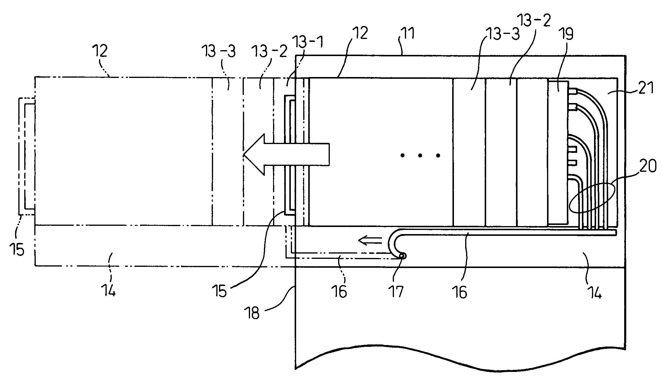
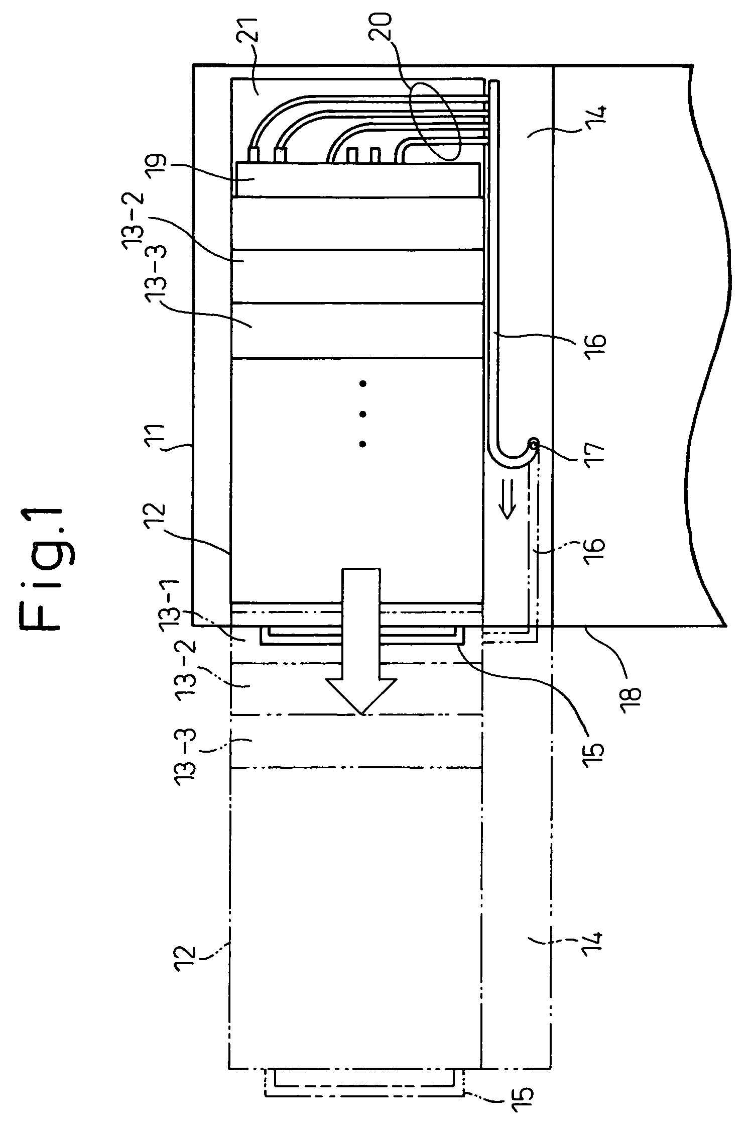
[0027]FIG. 1 is a side view showing the appearance of a magnetic disk loading apparatus in accordance with the first embodiment of the present invention. In the drawing, there are shown a magnetic disk loading apparatus 11, a disk enclosure 12, magnetic disk units 13-1, 13-2, 13-3, etc., a cable container 14, a pull 15 with which the disk enclosure is pulled out of the magnetic disk loading apparatus, and a flexible cable guide 16 realized with, for example, a locally procurable chain guide whose section has a oblong rectangular shape and to which a chain is attached.

[0028]The cable guide 16 accommodates signal lines, ac and dc power cables, and optical fibers that are coupled to the magnetic disk units 13-1, 13-2, etc. FIG. 1 shows only the cables coupled to the magnetic disk unit 13-1 among all the cables...


PUM


Abstract

Provided is a magnetic disk loading apparatus making it easy to perform the work of replacing a magnetic disk unit or any other component with a new one or the work of maintaining or inspecting it, and accommodating a larger number of magnetic disk units. A magnetic disk loading apparatus comprises magnetic disk units stored in a disk enclosure, and a cable container located in a place within the disk enclosure other than the place where the magnetic disk unit is located. The magnetic disk loading apparatus is designed so that the disk enclosure can be inserted into or pulled out of the magnetic disk loading apparatus from the front side of the magnetic disk loading apparatus. Cables contained in the cable container are coupled to the magnetic disk unit, and encased in a cable guide that can be bent or stretched along with the insertion or the pulling-out of the disk enclosure.

Description

BACKGROUND OF THE INVENTION[0001]1. Field of the Invention[0002]The present invention relates to a magnetic disk loading apparatus and, more particularly, to a magnetic disk loading apparatus including a cable container mechanism that makes it easy to maintain magnetic disk units or other components.[0003]2. Description of the Related Art[0004]A magnetic disk loading apparatus for loading numerous magnetic disk units is known.[0005]FIG. 5 is a perspective view showing the appearance of a conventional magnetic disk loading apparatus. In the drawing, there are shown a magnetic disk loading apparatus 51, disk enclosures 52, and magnetic disk units 53. As illustrated, the magnetic disk units 53 are stored in the disk enclosures 52 so that the face of the magnetic disk loading apparatus will be flush with the faces of the magnetic disk units 53. The disk enclosure 52 may have a multistory structure or a single-story structure.[0006]Referring to FIG. 5, the magnetic disk units 53 are moun...

Claims


Application Information

Patent Timeline
Patent Type & Authority Patents(United States)
IPC IPC(8): G06F1/16
CPCG11B33/126
Inventor WATANABE, TAKASHI
Owner FUJITSU LTD
Why Eureka
Try Eureka