Jet drive propulsion system for a pontoon boat

Inactive Publication Date: 2007-03-06
BRUNSWICK CORPORATION
View PDF24 Cites 31 Cited by
  • Summary
  • Abstract
  • Description
  • Claims
  • Application Information

AI Technical Summary

Benefits of technology

[0029]In a particularly preferred embodiment of the present invention, the container is removably attached to a platform of the pontoon boat with all components attached to the container being located completely below the upper surface of the platform. Elastomeric components can be used to isolate the container and its constituent components from the platform of the pontoon boat in order to decrease the amount of noise and vibration transmitted from the engine and marine drive device to the platform of the pontoon boat.
[0030]Various embodiments of the present invention will be described in detail below. These embodiments incorporate various advantageous characteristics of the present invention in selected combination with each other. One particularly advantageous characteristic is the placement of the engine completely below an upper surface of the deck which extends between flotation tubes of the pontoon boat. A door can be provided in the deck of the pontoon boat to allow easy access to the engine and other components disposed within the container while avoiding the necessity of having a bulge extending upwardly through the top surface of the deck. The engine i

Problems solved by technology

Known marine propulsion devices of the type described immediately above do not provide a sterndrive or jet drive propulsion device within a conta

Method used


Image

  • Jet drive propulsion system for a pontoon boat
  • Jet drive propulsion system for a pontoon boat
  • Jet drive propulsion system for a pontoon boat

Examples


Embodiment Construction

[0043]Throughout the description of the preferred embodiment of the present invention, like components will be identified by like reference numerals.

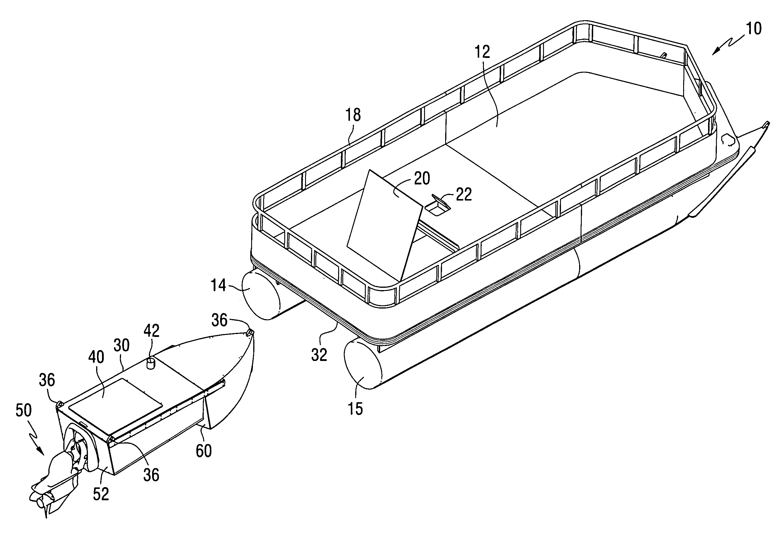
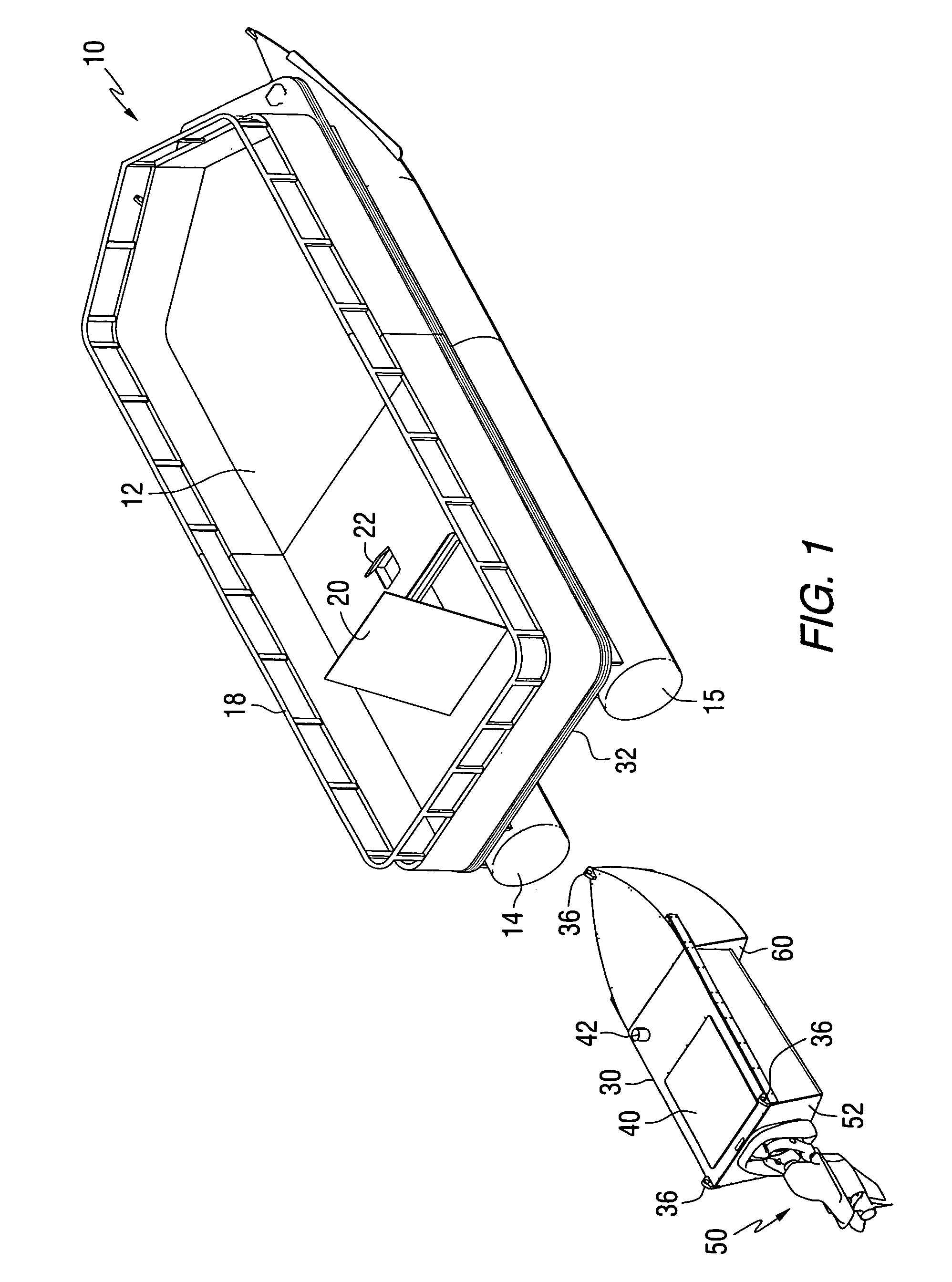
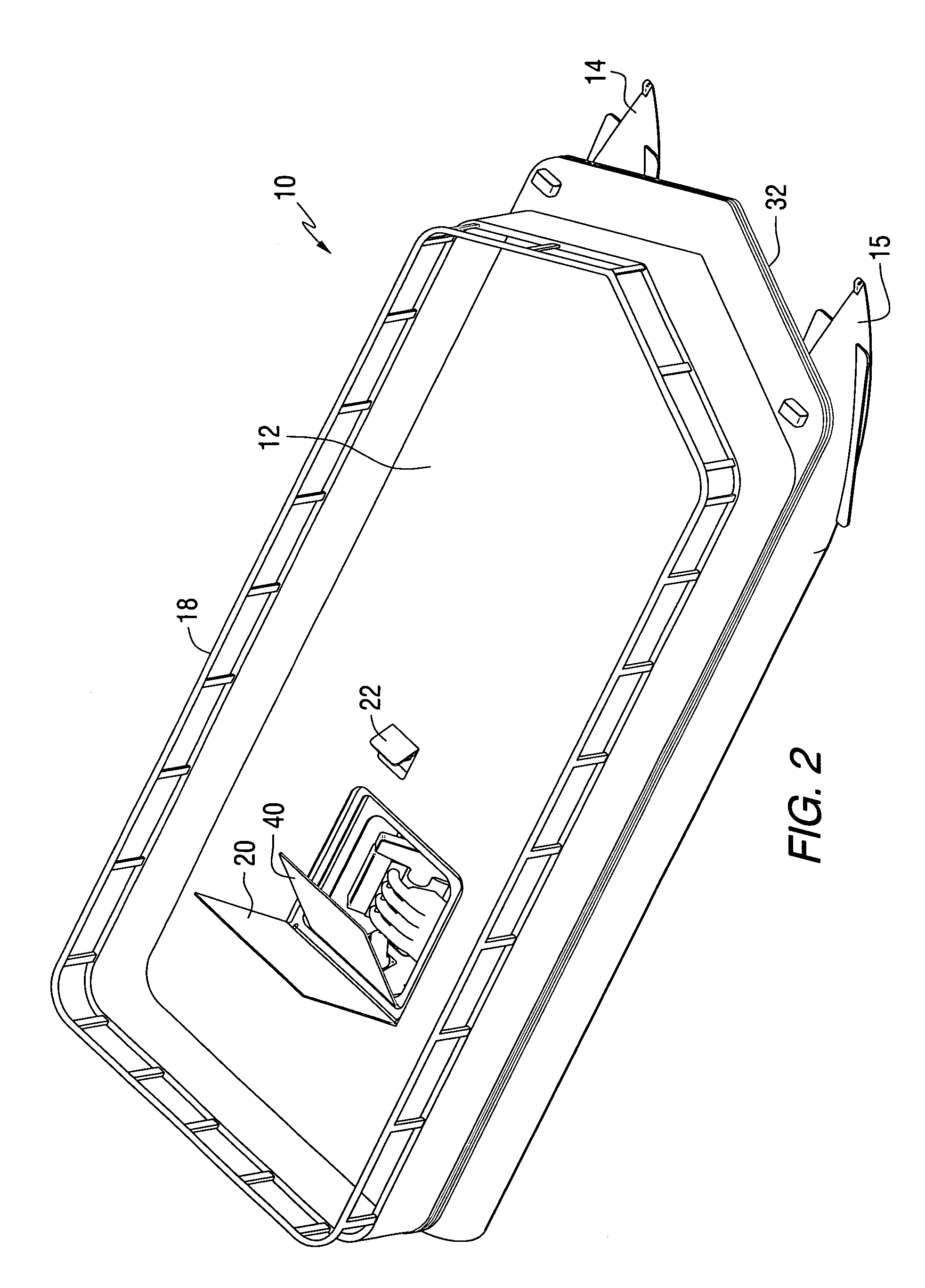
[0044]FIG. 1 shows a pontoon boat 10 that comprises a deck 12, or platform, supported by two flotation tubes, 14 and 15. The pontoon boat 10 is provided with a railing structure 18. An access door 20 is provided in the generally horizontal and planar surface of the deck 12. In addition, a fuel access door 22 is provided for purposes that will be described in greater detail below.

[0045]With continued reference to FIG. 1, a container 30, or pod, is removably attachable to an underside 32 of the pontoon boat 10. This removable attachability can be accomplished through the provision of mounts 36 attached to the container 30 and shaped to cooperate with similarly configured mounts attached to the underside 32 of the deck 12. The container 30 is provided with a container door 40 which allows access to the inner cavity of the container 30 as w...


PUM


Abstract

A pontoon boat is provided with a jet drive propulsion system in which an impeller is driven by an engine. The jet drive propulsion device is dirigible as a result of the fact that a nozzle of the device is rotatable about a generally vertical steering axis. The jet drive device can be supported below a deck of a pontoon boat and located between two flotation tubes of the pontoon boat. Alternative locations can also be used, such as within the structure of the flotation tubes themselves.

Description

BACKGROUND OF THE INVENTION[0001]1. Field of the Invention[0002]The present invention is generally related to marine propulsion systems for a pontoon boat and, more particularly, to a jet drive propulsion system for a pontoon boat.[0003]2. Description of the Related Art[0004]Those skilled in the art of marine propulsion systems are aware of many different types and styles of pontoon boats. As used herein, the term “pontoon boat” shall mean a marine vessel which supports a deck surface on flotation devices. The flotation devices, in a typical application of a pontoon boat, are hollow or foam-filled tubes that are arranged in generally parallel relation with each other. The deck, or platform, of the pontoon boat extends across the upper portions of the flotation tubes. In most applications, a majority of the deck surface is a flat horizontal plane.[0005]In a typical application, a pontoon boat is provided with an outboard motor that is attached to a rear portion of the support structu...

Claims


Application Information

Patent Timeline
IPC IPC(8): B63B21/56
CPCB63B35/665B63B1/12
Inventor GRIFFITHS, JOHN M.JASZEWSKI, WAYNE M.PHILLIPS, GEORGE E.DAVIS, RICHARD A.
Owner BRUNSWICK CORPORATION
Why Eureka
Try Eureka