Fastening tool apparatus and method for operating the engine of fastening tool

a technology of fastening tool and engine, which is applied in the direction of power driven tools, drilling machines and methods, nailing tools, etc., can solve the problems of the mechanism by which the magazine assembly is mounted to the tool, adds a significant amount of weight and length to the tool, etc., to reduce the overall weight and length of the tool, reduce the complexity of the pneumatic circuitry, and reduce the weight of the fastening tool

Inactive Publication Date: 2007-03-06
BLACK & DECKER INC
View PDF63 Cites 20 Cited by
  • Summary
  • Abstract
  • Description
  • Claims
  • Application Information

AI Technical Summary

Benefits of technology

[0005]In one form, the teachings of the present invention provide a fastening tool that employs a unique head valve to reduce the weight of the fastening tool. In another form, the teachings of the present invention provide a method for operating a fastening tool. A fastening tool constructed in accordance with the teachings of the present invention may employ an engine with a sliding sleeve arrangement which can reduce the complexity of the pneumatic circuitry of the fastening tool and thereby reduce the overall weight and length of the tool.

Problems solved by technology

One such drawback concerns the main valve in that it adds a significant amount of weight and length to the tool.
Another drawback concerns the mechanism by which the magazine assembly is mounted to the tool.

Method used


Image

  • Fastening tool apparatus and method for operating the engine of fastening tool
  • Fastening tool apparatus and method for operating the engine of fastening tool
  • Fastening tool apparatus and method for operating the engine of fastening tool

Examples


Embodiment Construction

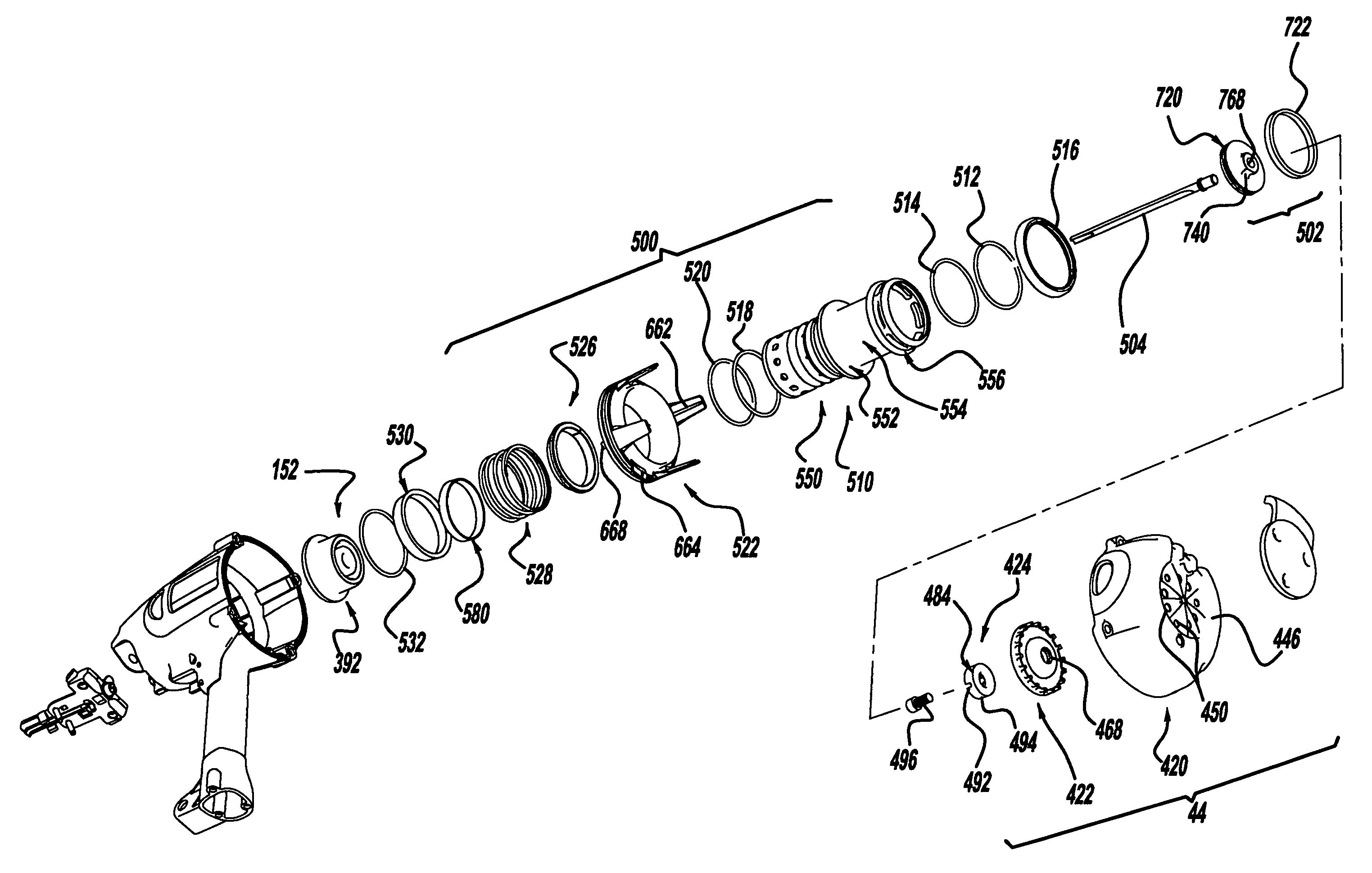
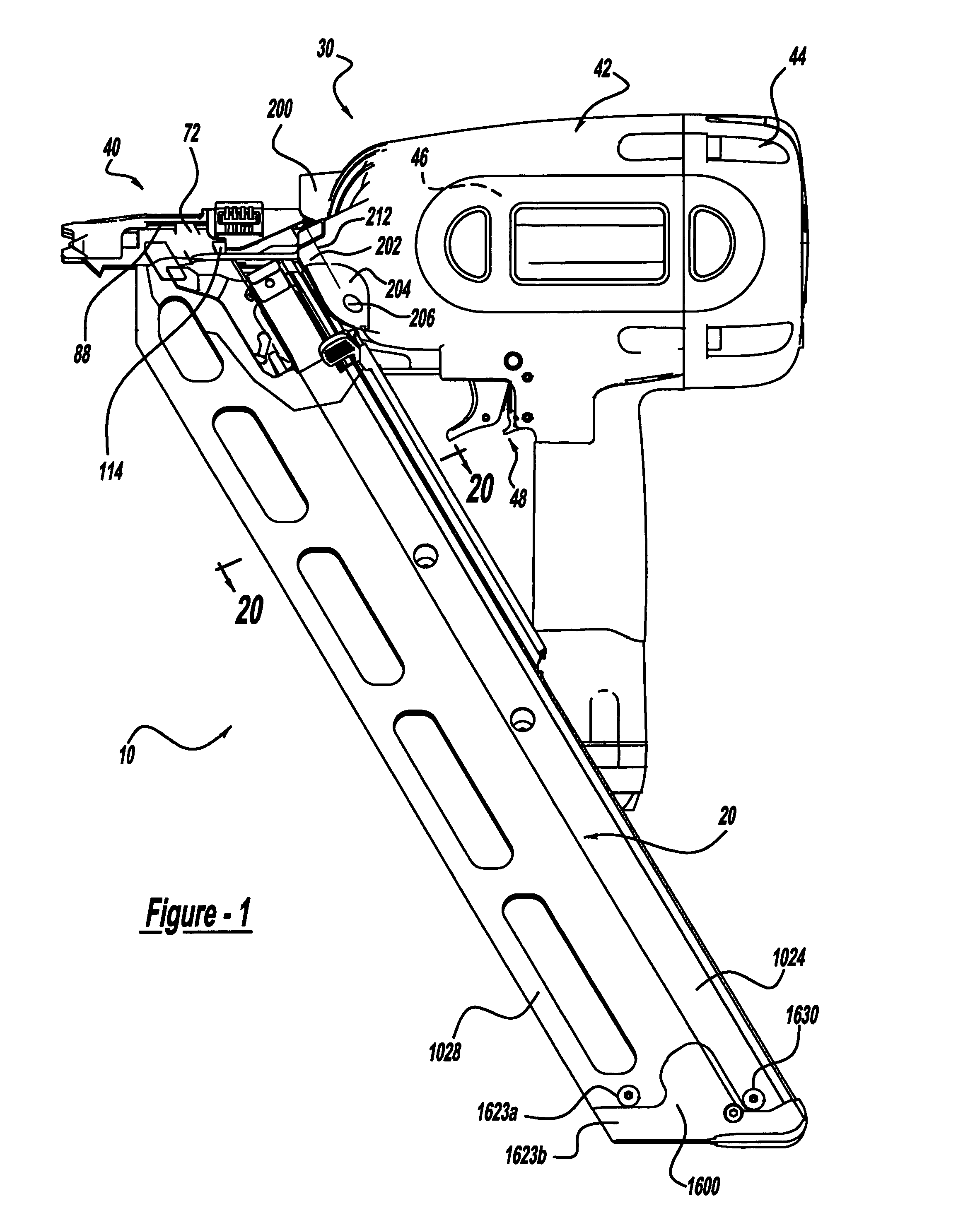
[0058]With reference to FIG. 1 of the drawings, a fastening tool constructed in accordance with the teachings of the present invention is generally indicated by reference numeral 10. Fastening tool 10 is illustrated to include a detachable magazine assembly 20 and a fastening tool portion 30. The fastening tool portion 30 includes a nose assembly 40, a housing assembly 42, a cap assembly 44, an engine assembly 46 and a trigger assembly 48.

Nose Assembly

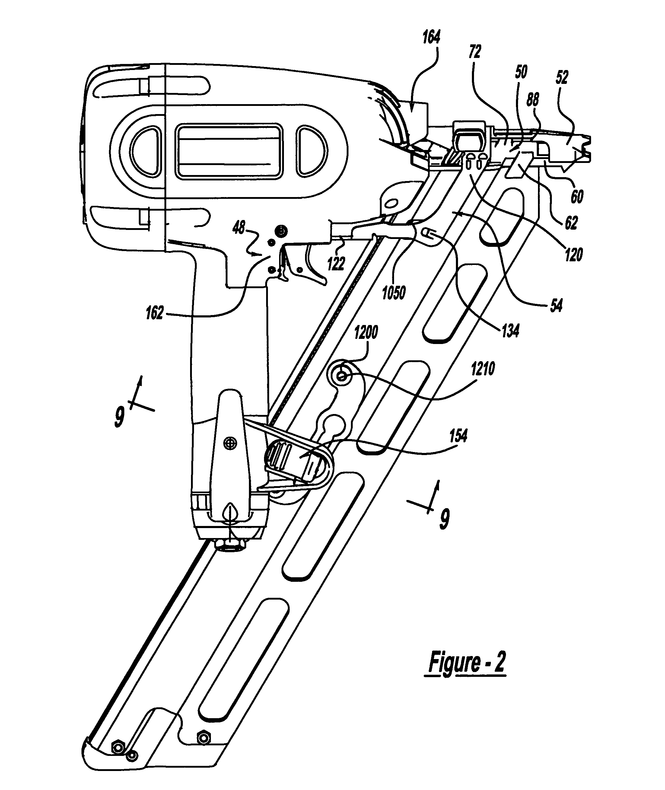
[0059]With reference to FIGS. 1 through 9, the nose assembly 40 is illustrated to include a nose structure 50, a contact trip 52, a trigger lever 54 and a contact trip-return spring 56. The nose structure 50 includes a nose body 60, a pair of magazine stabilizing tabs 62, a magazine flange 64, a pair of magazine guide posts 66, a mounting base 68, a spring post 70 and a pair of contact trip guides 72. The nose body 60 is generally U-shaped, with the legs 80 of the “U” being inwardly offset to form a semi-circular blade cavity 82. The i...


PUM

PropertyMeasurementUnit
diameteraaaaaaaaaa
angleaaaaaaaaaa
angleaaaaaaaaaa

Abstract

A pneumatic fastening tool assembly that employs an engine having a sliding sleeve arrangement to control the supply of air to and exhaust from the pneumatic engine. The sliding sleeve arrangement eliminates the need for a conventional main valve and thereby reduces the overall weight and length of the pneumatic fastening tool relative to those tools that employ a conventional engine configuration.

Description

CROSS-REFERENCE TO RELATED APPLICATIONS[0001]This application is divisional application of U.S. patent application Ser. No. 10 / 428,605 filed May 2, 2003 now U.S. Pat. No 6,938,812, which is a continuation of U.S. patent application Ser. No. 10 / 072,603 filed Feb. 7, 2002, which issued as U.S. Pat. No. 6,609,646 and which claimed the benefit of U.S. Provisional application No. 60 / 267,359, filed Feb. 8, 2001. Other features of the present invention are discussed and claimed in commonly assigned U.S. Pat. Nos. 6,648,202, 6,679,413 and 6,772,931.FIELD OF THE INVENTION[0002]The present invention generally relates to a pneumatically actuated device for driving fasteners fed from a magazine into a workpiece and more specifically to a pneumatic engine that employs a shifting cylinder sleeve to control the supply of air to and exhaust from the pneumatic engine.BACKGROUND OF THE INVENTION[0003]A number of pneumatically operated devices have been developed for use in driving fasteners, such as ...

Claims


Application Information

Patent Timeline
Patent Type & Authority Patents(United States)
IPC IPC(8): B25C1/00B25C1/04B25C1/16
CPCB25C1/005B25C1/008B25C1/046B25C1/045B25C1/044
Inventor MILLER, KEVEN EFUNICELLO, JOHN CHAGAN, TODD AMILLER, THOMAS E
Owner BLACK & DECKER INC
Why Eureka
Try Eureka