Fastcan

a technology of fastcan and container, applied in the field of outdoor refuse containers, can solve the problems of difficult and near impossible sweeping, raking, and moving the refuse into the container, and achieve the effect of easy lifting uprigh

Active Publication Date: 2007-03-06
XTREME PLASTICS
View PDF31 Cites 51 Cited by
  • Summary
  • Abstract
  • Description
  • Claims
  • Application Information

AI Technical Summary

Benefits of technology

[0014]A primary objective of the invention is to provide a novel refuse container with a triangular-torpedo shaped flat

Problems solved by technology

However, the upright standing position generally requires the user having to physically bend and pickup the refuse with one's hands to place it into the standing container.
In addition to the undesirable physical movements, it is usually undesirable to physically touch the refuse even if one uses gloves.
Furthermore, physically lifting up and moving the refuse usually results in some debris dropping out and having to be picked up again.
However, the circular opening to the container makes it difficult and near impossible to sweep, rake, and move the refuse into the container.
However, the circular opening is not meant to bend, and also, the user can slip, fall and get hurt trying to stand on the sides of a plastic container.
However, these containers have their opening ends having at least and preferably larger interior diameter sized spacing than their closed ends, which makes the containers difficult if not impossible to stand on their closed bottom ends.
Furthermore, filling these containers with debris creates an unstable container since the interior weight is concentrated toward the upper open ends and would tend to cause the containers to fall over spilling their contents out.
Furthermore, all of these containers must be physically lifted and carried to be moved which makes them difficult when filled to be mobile.
Leatherman '183, Fuhr '476, Wade '531, Lichtenwalner '588 and Cates '495 each describe debris container having side walls forming rectangular shapes that also have their open ends be larger in interior cross-section than their closed bottom interior ends so that filling up the containers causes a stability problem when trying to vertically stand the container up since more weight is adjacent the upper open end than the closed end.
These containers would also tend to fall over and spill their contents out.
The containers are not very stable when filled with debris and can easily tip over and spill the container contents when being used.
Further, Presnell '235 and Burgan '888 only have handles on left and right sides of the containers which make it difficult to lift from horizontal to standing positions and vice versa.
Also, both containers have raised rectangular shaped lip edges adjacent their upper open ends making it difficult to push debris over the bump like edges into the containers.
Additionally, the small flat mouth edges of these references are much too small to allow trad

Method used


Image

  • Fastcan
  • Fastcan
  • Fastcan

Examples


first embodiment

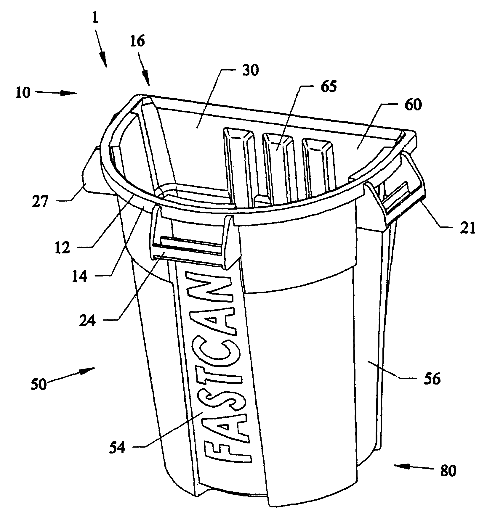
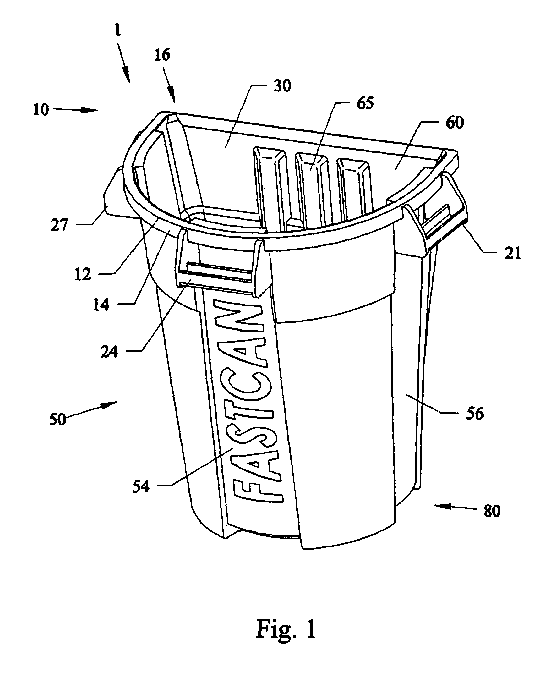
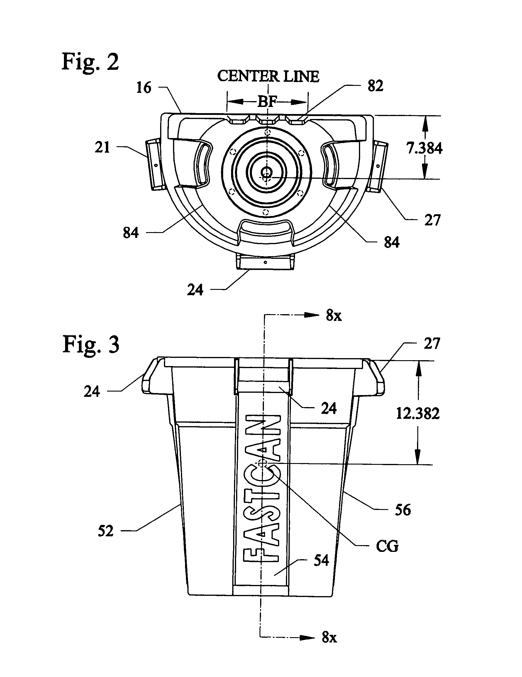
[0069]FIG. 1 is a front upper right perspective view of the novel outdoor refuse container 1. FIG. 2 is a bottom view of the container 1 of FIG. 1 showing the substantially circular configuration bottom end 80. FIG. 3 is a front view of the container 1 of FIGS. 1–2. FIG. 4 is a rear view of the container 1 of FIGS. 1–3 showing the triangular-tubular shaped flat side wall portion 60. FIG. 5 is a top view of the container 1 of FIGS. 1–4. FIG. 6 is a side view of the container 1 of FIGS. 1–5. FIG. 7 is a side view of stacked containers 1, 1′, 1″. FIG. 8 is a cross-sectional view of the container 1 of FIG. 3 along arrows 8X. FIG. 8A is an enlarged view of the sloping scoop edge portion 16 with rounded blunt end and slopping ramp portion.

[0070]Referring to FIGS. 1–8A, a first embodiment container 1 can be formed in a single piece from injection molded plastic, and the like, and have an open upper end portion 10 that can include a substantially D-shaped cross-sectional configuration defin...

embodiment 600

[0088]FIG. 24 is another embodiment 600 showing molded side support members 620, 610 on the novel container 1 of the preceding embodiment for supporting long handled tools 720 such as rakes, brooms and shovels therein. An upper support member 620 molded onto the side of the container 1 can have a through-hole therethrough for allowing the long handle 715 of the implement to slide therethrough. A lower support member 610 adjacent to the bottom end 80 of the container 1 can be funnel shaped with a larger top opening 611 than a bottom opening 619 so that water can drain through the holder 610 but still support and hold a tip end of a longitudinal handle 715 inside the holder 610. The holders 610 and 620 can allow for tools to be held close to and parallel to the sides of the container 1 so that users can move both the container 1 and the implements 720 together to work sites.

[0089]While long handle tools are shown being held and supported in the preceding figures, the invention can be ...


PUM


Abstract

Outdoor and indoor debris receptacles that can be formed from molded plastic. The receptacles include an open upper end with a D-shaped configuration and a closed bottom end with a substantially circular bottom configuration. The receptacles can have a generally cylindrical shape and a flat side wall having a triangular tubular shape for allowing the receptacle to be laid on its side so that rakes and brooms can move debris fully into the D-shaped opening with ease. At least one handle located on the apex of the D-shaped opening allows the container to be easily lifted to a vertical standing position, and curved interior wall surfaces allow debris to easily slide toward the bottom of the container. Embodiments allow for different sizes of container, and extras such as lids, wheels and supports for tools. such as but not limited to rakes, hoes, and shovels to be carried and stored by the receptacles.

Description

[0001]This invention claims the benefit of priority to U.S. Provisional Application No. 60 / 405,452 filed Aug. 23, 2002.FIELD OF INVENTION[0002]This invention relates to outdoor refuse containers, and in particular to novel refuse containers and methods of use where the container can be easily laid on flat side portions so that debris can be completely swept inside the container, and remain stable and sturdy when full and standing upright.BACKGROUND AND PRIOR ART[0003]It is common to use refuse containers such as plastic tubular cans for holding outdoor refuse such as leaves, branches, garbage, and the like. Typically, these containers must be kept in an upright standing position to be used. However, the upright standing position generally requires the user having to physically bend and pickup the refuse with one's hands to place it into the standing container. In addition to the undesirable physical movements, it is usually undesirable to physically touch the refuse even if one uses...

Claims


Application Information

Patent Timeline
IPC IPC(8): B65D21/00
CPCB65F1/14B65F1/1468B65F1/1646B65F2230/00B65F2240/138Y10S220/908B65F2220/12
Inventor MILLER, DAVID H.
Owner XTREME PLASTICS
Why Eureka
Try Eureka