Bracket mounting structure of propeller shaft

a technology of mounting structure and propeller shaft, which is applied in the direction of machine supports, shock absorbers, washers, etc., can solve the problems of insufficient reliability of such adhesives, shortening the life of adhesives, and needing additional countermeasures, etc., to achieve the effect of improving the mounting structure of brackets

Inactive Publication Date: 2007-03-06
SHOWA CORP
View PDF25 Cites 15 Cited by
  • Summary
  • Abstract
  • Description
  • Claims
  • Application Information

AI Technical Summary

Benefits of technology

[0011]An object of the present invention is to improve a bracket mounting structure for elastically supporti...

Problems solved by technology

Further, there is a fear of a shortage of parts.
Although it would be possible to fix the element together by an adhesive agent, in this case, since a degreasin...

Method used


Image

  • Bracket mounting structure of propeller shaft
  • Bracket mounting structure of propeller shaft
  • Bracket mounting structure of propeller shaft

Examples


Embodiment Construction

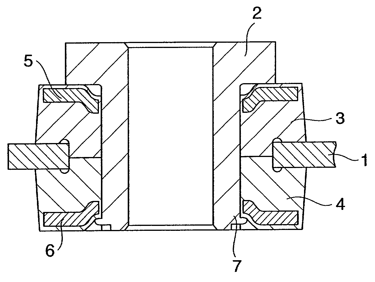
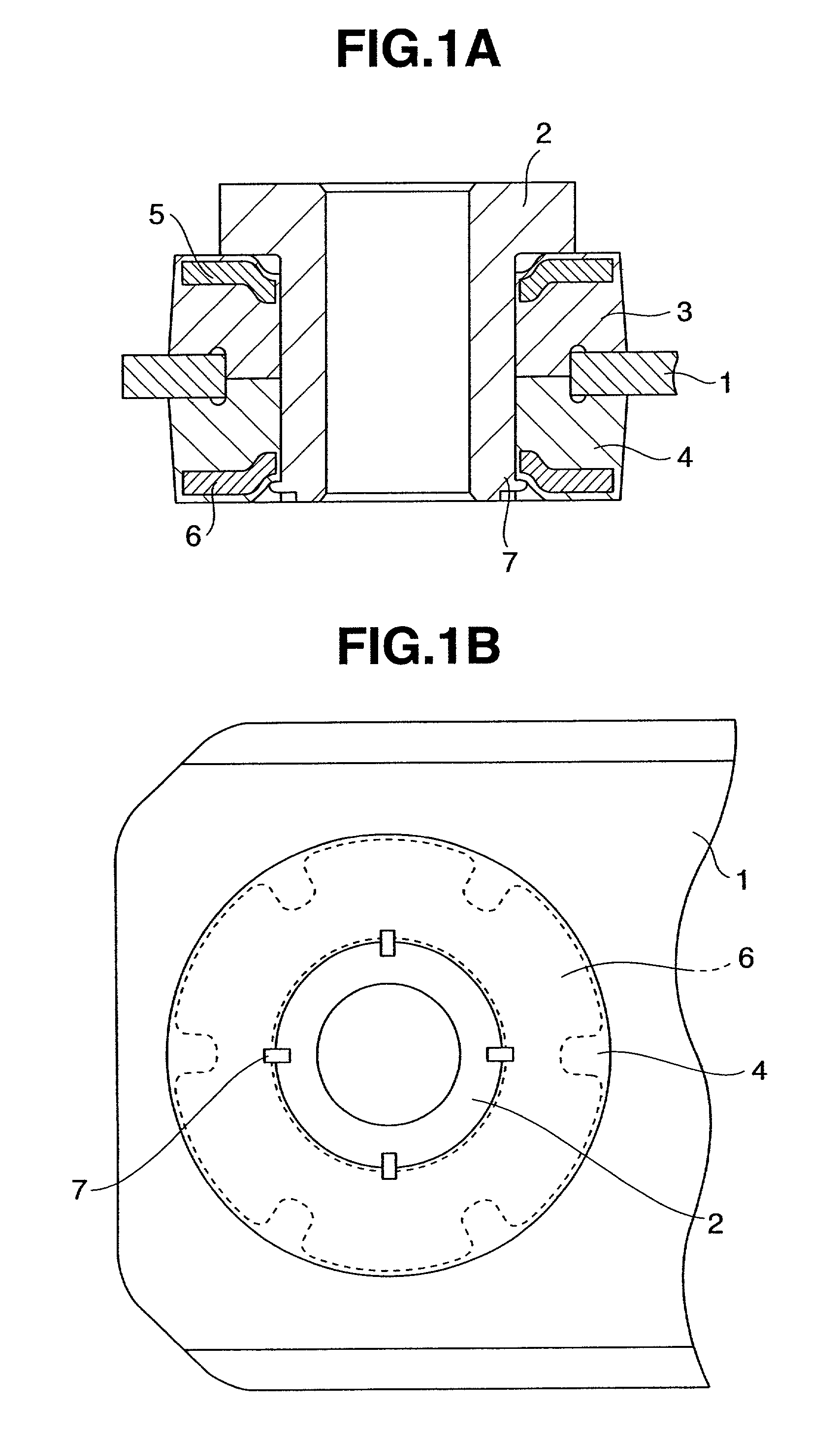
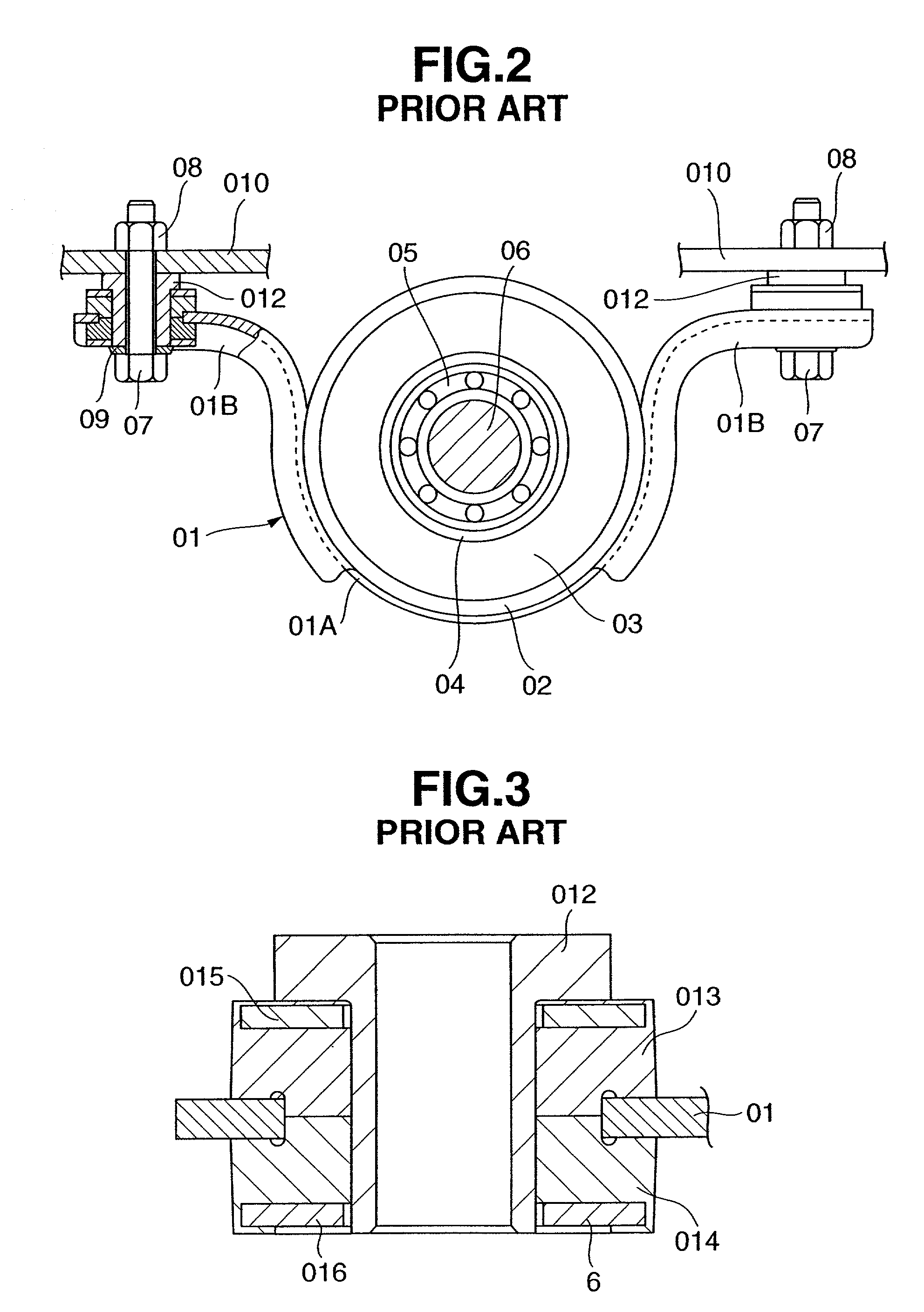
[0018]FIG. 1A is a vertical cross sectional view showing an example according to the present invention. FIG. 1B is a bottom elevational view of the same. In these drawings, for convenience of understanding, a vehicle body member, mounting bolts and the like are not illustrated, and there is shown a portion of the device in which only a mounting element is mounted to a bracket, that is, a state corresponding to FIG. 3.

[0019]As shown in FIGS. 1A and 1B, according to the present example, in the same manner as the conventional one, a pair of upper and lower rubber bushes 3 and 4 are fitted to an outer periphery of a cylindrical bush collar 2 having a flange at an upper end so as to grip a bracket 1 there-between. Washers 5 and 6 are respectively arranged in an upper end of the upper rubber bush 3 among the rubber bushes and a lower end of the lower rubber bush 4 by being integrally fixed by baking or similar means. An upper surface of the washer 5 and a lower surface of the washer 6 are...


PUM


Abstract

In a bracket mounting structure is disclosed for mounting a bracket holding a center bearing of a propeller shaft to a vehicle body member by bolts and nuts. The structure contains a bush collar formed in a cylindrical shape having a flange in an upper end, fitted to the bolts and fixed to the vehicle body member by the bolts and the nuts. It also contains a pair of upper and lower rubber bushes fitted to an outer periphery of the bush collar and gripping the bracket there-between, and a washer provided in a lower end of the lower rubber bush among the rubber bushes. An outer peripheral edge of a lower end of the bush collar extends all through an inner peripheral edge of the washer and is expanded outward in diameter.

Description

BACKGROUND OF THE INVENTION[0001]1. Field of the Invention[0002]The present invention relates to a bracket mounting structure for elastically supporting a center bearing provided in a middle portion of a propeller shaft in a motor vehicle to a vehicle body member.[0003]2. Description of the Related Art[0004]A conventional bracket mounting structure includes, for example, structures disclosed in Japanese Utility Model Application Publication No. 7-39697 and Japanese Utility Model No. 2589855. Next, a description will be given of a basic structure of the conventional bracket mounting structure mentioned above with reference to the accompanying drawings.[0005]FIG. 2 is a partly cut-out front elevational view showing one example of a conventional bracket mounting structure which includes a propeller shaft and a center bearing.[0006]A propeller shaft passing under a lower surface of a floor in a motor vehicle is structured such that a middle portion thereof is supported in a rotating man...

Claims


Application Information

Patent Timeline
IPC IPC(8): F16M13/00B60K17/24F16F1/373F16F15/08
CPCF16F1/3732B60K17/24B60G2204/41B60G2204/44
Inventor SUKA, TEIJINAOI, MASARUIWANO, KAZUHIRO
Owner SHOWA CORP
Why Eureka
Try Eureka