Surface acoustic wave filter

a surface acoustic wave and filter technology, applied in piezoelectric/electrostrictive/magnetostrictive devices, piezoelectric/electrostriction/magnetostriction machines, electrical equipment, etc., can solve the problem that the known technique described in patent document 1 does not sufficiently meet the above-described requirements, and the insertion loss is large, so as to reduce bandwidth, improve shape factor, and increase filter size

a surface acoustic wave and filter technology, applied in piezoelectric/electrostrictive/magnetostrictive devices, piezoelectric/electrostriction/magnetostriction machines, electrical equipment, etc., can solve the problem that the known technique described in patent document 1 does not sufficiently meet the above-described requirements, and the insertion loss is large, so as to reduce bandwidth, improve shape factor, and increase filter size

US7187101B2Active Publication Date: 2007-03-06MURATA MFG CO LTD

Image

  • Surface acoustic wave filter
  • Surface acoustic wave filter
  • Surface acoustic wave filter

Examples


Embodiment Construction

[0039]Hereinafter, the present invention will be made clear by description of the preferred embodiments of the present invention made with reference with the accompanying drawings.

[0040]First Preferred Embodiment

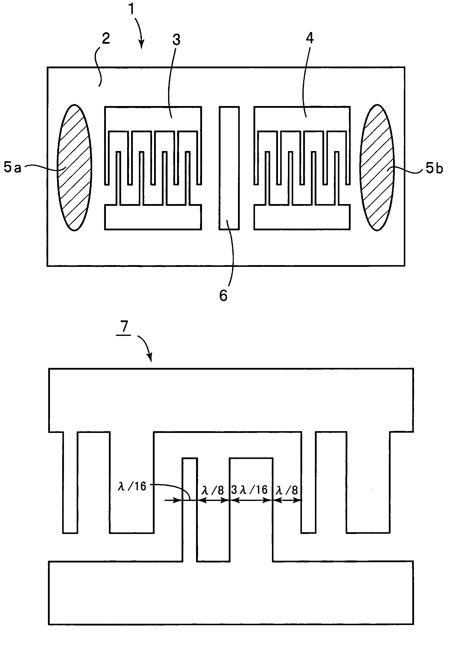
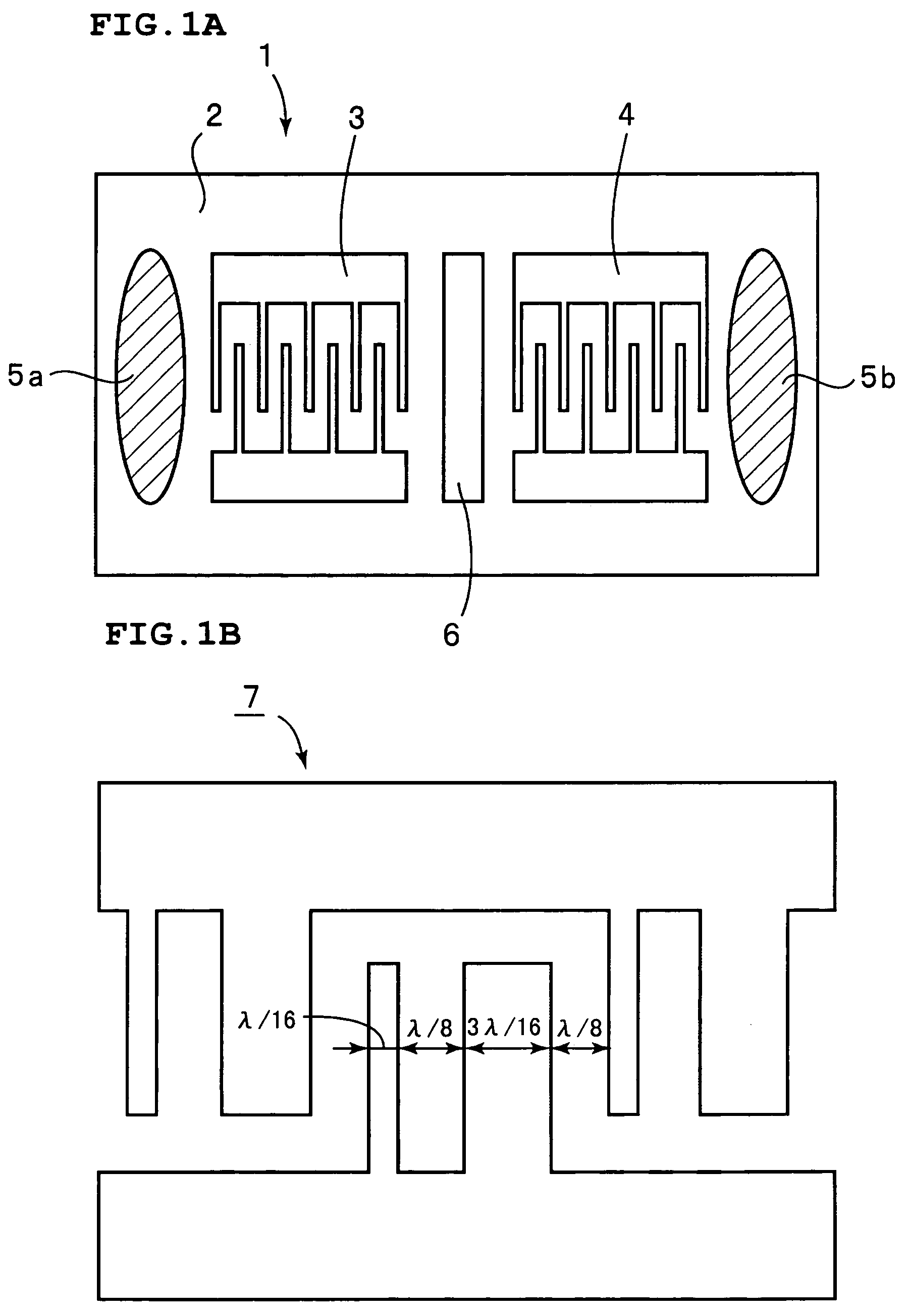
[0041]FIG. 1A is a schematic plan view of a surface acoustic wave filter according to a preferred embodiment of the present invention, and FIG. 1B is a schematic plan view of SPUDT used in the surface acoustic wave filter.

[0042]A surface acoustic wave filter 1 preferably includes an ST-cut crystal substrate 2, e.g., having an Euler's angle (0, 116, 0). An input-side IDT electrode 3 and an output-side IDT electrode 4 are arranged on the crystal substrate 2 so as to be separated from each other in the propagation direction of a surface acoustic wave. Moreover, a shield electrode 6 is provided between the IDT electrodes 3 and 4. In this preferred embodiment, each of the input-side IDT electrode 3 and the output-side IDT electrode 4 preferably includes an SPUDT electrode 7 havin...


PUM


Abstract

In a surface acoustic wave filter, an input-side IDT electrode and an output-side IDT electrode are arranged on a piezoelectric substrate so as to be separated from each other in the propagation of a surface acoustic wave. The thickness of the IDT electrodes is set so that the first coefficient of the velocity-dispersion has a negative value.

Description

BACKGROUND OF THE INVENTION[0001]1. Field of the Invention[0002]The present invention relates to a surface acoustic wave filter for use as, e.g., a band filter and, more particularly, to a transversal type surface acoustic wave filter in which an electrode including an electrode layer of Al or an Al alloy is provided on a crystal substrate.[0003]2. Description of the Related Art[0004]Known transversal type surface acoustic wave filters are used as IF filters in portable telephones. However, the transversal type surface acoustic wave filters have problems in that the insertion loss is large.[0005]Thus, heretofore, different types of surface acoustic wave filters have been proposed which include unidirectional electrodes for reducing the insertion loss.[0006]IEICE Trans. '86 / 10 Vol. J69-C No. 10 (p 1297–1308) (Non-patent Document 1) describes a method of designing a SPUDT (Single Phase Uni-Directional Transducer) which is a kind of unidirectional electrode. According to the descriptio...

Claims


Application Information

Patent Timeline
06 Mar 2007
Publication
US7187101B2
IPC
H03H9/25; H03H9/46; H03H9/02; H03H9/145
CPC
H03H9/14541; H03H9/14505; H03H9/02551
Inventors
KIDOH, HIDEO