Use of within-field-element-size CV for improved nutrient fertilization in crop production

a technology of within-field elements and fertilizers, applied in the field of method for determining the rate of fertilizer application, can solve problems such as poor plant conditions

Inactive Publication Date: 2007-03-13
BOARD OF REGENTS FOR OKLAHOMA STATE UNIVERSITY
View PDF33 Cites 53 Cited by
  • Summary
  • Abstract
  • Description
  • Claims
  • Application Information

AI Technical Summary

Benefits of technology

[0019]The present invention provides a method for determining in-season macro and micronutrient application based on predicted yield potential, as adjusted by the coefficient of variation (“CV”) of the crop within the sensed area as measured by an optical, or other, sensor, and a nutrient response index. In a preferred embodiment of the inventive method, remote sensing is employed to determine plant need for a particular nutrient and to determine mid-season yield potential. In a preferred embodiment, an optical sensor is used to measure the reflectance of a target plant, or plants, within a particular plot, at one or more wavelengths of light and, based on known reflectance properties of the target; an output is provided which is indicative of the need for the nutrient. Intraplot sensor readings are also taken to determine the coefficient of variation (“CV”) of plant condition within the plot. Where CV is high, the potential yield is adjusted downward to account for factors, which will limit production other than nutrient stress. The inventive process is applicable to crop nutrients whose projected need can be based on predicted removal of the nutrient derived from potential yield. The inventive process is particularly well suited to the mid-season application of nitrogen and / or other nutrients where deficiencies can be corrected by mid-season applications.
[0020]In another preferred embodiment, for crops in which plant height is indicative of yield, i.e. corn, a sensor, such as an ultrasonic or radar sensor, is used to measure plant height. Intraplot variations in plant height are used to determine the CV of plant condition within the plot. As with the optical sensor, where CV is high, the maximum potential yield is adjusted downward to account for factors, other than nutrient stress, which will limit production.
[0021]Generally speaking, where factors affecting soil productivity, i.e., soil depth, slope, moisture holding capacity, soil compaction, and the like, are uniform, CV's are expected to be relatively homogenous and low. Under such conditions, one would expect uniform plant stands and uniform plant growth. In contrast, where factors affecting soil productivity vary widely, CV's are expected to be relatively high. Under growing conditions with a high CV, poor plant conditions may be caused by mechanical problems combined with specific soil conditions rather than by lack of available nutrients.
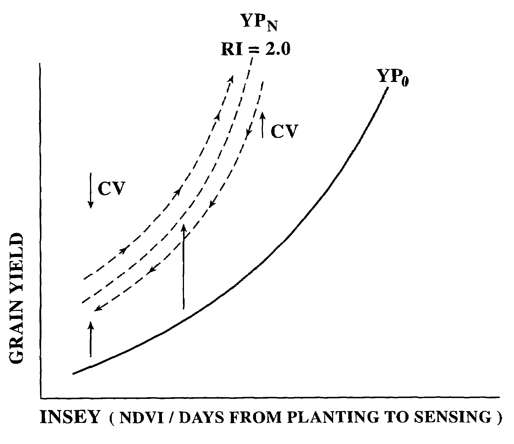
[0022]Efficiency of site-specific nutrient management is largely determined by how well small-scale spatial variability is managed and the time when fertilizers are applied. During the crop growing-season (in-season), knowledge of yield potential is a key to successful variable rate nutrient applications. The dependency of the yield potential with an added nutrient to sensed and known factors may be expressed as a function of the normalized difference vegetation index (“NDVI”), the number of days the crop has been growing, and the coefficient of variation of NDVI measurements within the plot being assessed for nutrient fertilization.
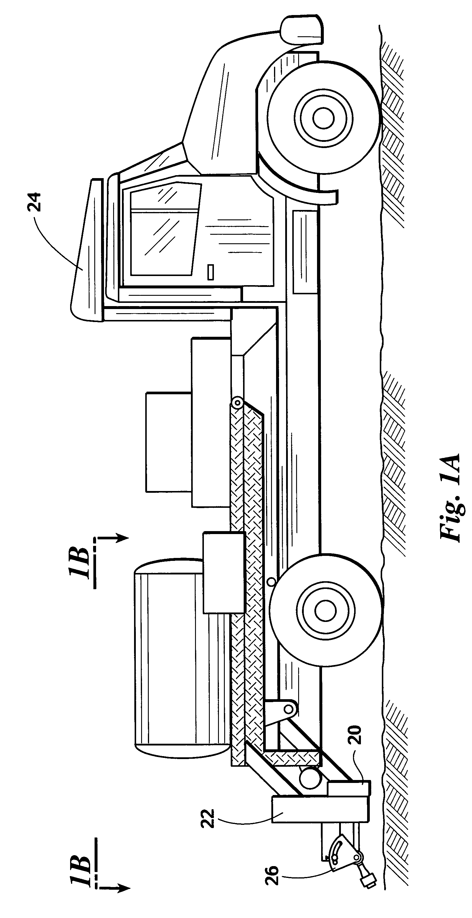
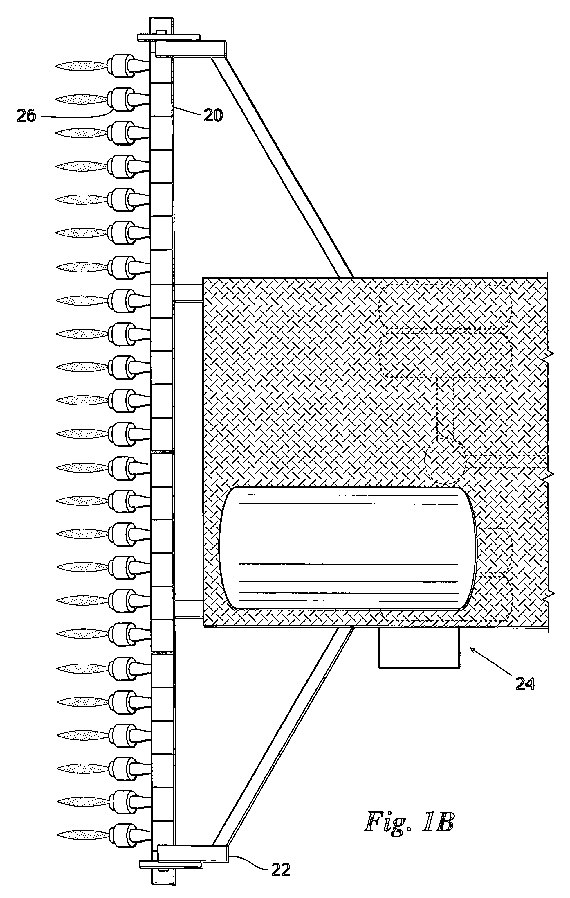
[0023]In the inventive method, the normalized difference vegetation index is preferably calculated from reflectance information gathered by scanning a plant or plants within an area scanned and treated. Virtually any method of measuring the reflectance, or other measure of plant growth, of individual plants or small groups of plants will provide the desired results. As a practical matter however, to determine CV, the resolution of the sensor must allow for successive measurements within a plot. In one preferred embodiment of the inventive method, as many as 70 reflectance measurements are taken within a 0.4 square meter area.

Problems solved by technology

Under growing conditions with a high CV, poor plant conditions may be caused by mechanical problems combined with specific soil conditions rather than by lack of available nutrients.

Method used


Image

  • Use of within-field-element-size CV for improved nutrient fertilization in crop production
  • Use of within-field-element-size CV for improved nutrient fertilization in crop production
  • Use of within-field-element-size CV for improved nutrient fertilization in crop production

Examples


Embodiment Construction

[0032]Before explaining the present invention in detail, it is important to understand that the invention is not limited in its application to the details of the construction illustrated and the steps described herein. The invention is capable of other embodiments and of being practiced or carried out in a variety of ways. It is to be understood that the phraseology and terminology employed herein is for the purpose of description and not of limitation.

[0033]As will become apparent to those skilled in the art from the discussion hereinbelow, practice of the present invention potentially increases crop yield while reducing the total amount of nutrients, such as nitrogen, added to a crop. While the inventive method is applicable to virtually any crop, for purposes of example, and not by way of limitation, the description of the preferred embodiments is directed to production of winter wheat. In practice, preferably side-by-side reference strips are planted along with the crop. A first...


PUM


Abstract

A method for in-season macro and micronutrient application based on predicted yield potential, coefficient of variation, and a nutrient response index. The inventive method includes the steps of: determining a nutrient response index for a field; determining the normalized difference vegetation index (NDVI) of an area to fertilize; determining the coefficient of variation of NDVI over a plot; determining a predicted crop yield for the area without additional nutrient; determining an attainable crop yield for the area with additional nutrient; determining the nutrient requirement for the area as the difference between the nutrient removal at the attainable yield minus the nutrient removal at the predicted yield, adjusted by the efficiency of nutrient utilization in the particular crop as indicated by the coefficient of variation.

Description

CROSS REFERENCE TO RELATED APPLICATION[0001]This application is a continuation-in-part of U.S. patent application Ser. No. 10 / 195,138, filed Jul. 12, 2002, now U.S. Pat. No. 6,880,291, which is a continuation-in-part of U.S. patent application Ser. No. 09 / 911,867, filed Jul. 24, 2001, now U.S. Pat. No. 6,601,341.BACKGROUND OF THE INVENTION[0002]1. Field of the Invention[0003]This invention relates generally to a method for determining a rate of application of fertilizer. More particularly, but not by way of limitation, the present invention relates a method for in-season macro and micronutrient application using within-element-size coefficient of variation to improve a prediction of yield potential, and hence, to more accurately predict the nutrient requirements of the crop.[0004]2. Background[0005]Presently, there is a need for a convenient method to determine the amount of fertilizer required to optimize the yield of a particular crop. While soil samples may be analyzed to determi...

Claims


Application Information

Patent Timeline
Patent Type & Authority Patents(United States)
IPC IPC(8): A01C21/00A01G7/00
CPCA01C21/007
Inventor RAUN, WILLIAM R.JOHNSON, GORDON V.SOLIE, JOHN B.STONE, MARVIN L.FREEMAN, KYLE
Owner BOARD OF REGENTS FOR OKLAHOMA STATE UNIVERSITY
Why Eureka
Try Eureka