Sliding load floor system with levitation mechanism

a floor system and sliding technology, applied in the direction of transportation and packaging, transportation items, transportation vehicles, etc., can solve the problems of back and other physical injuries, abbreviated length restricting the ability of the vehicle operator,

Inactive Publication Date: 2007-03-13
INT AUTOMOTIVE COMPONENTS GRP NORTH AMERICA INC
View PDF25 Cites 48 Cited by
  • Summary
  • Abstract
  • Description
  • Claims
  • Application Information

AI Technical Summary

Problems solved by technology

Abbreviated length restricts the ability of the vehicle operator who wishes to ergonomically transport longer or heavier items that would otherwise be accommodated by vehicles having a longer bed.
This may be inconvenient for cleanliness reasons (e.g., the soiling of clothes from a dirty outside vehicle surface).
Further, the act of reaching over to retrieve a heavy object may result in back and other physical injury.

Method used


Image

  • Sliding load floor system with levitation mechanism
  • Sliding load floor system with levitation mechanism
  • Sliding load floor system with levitation mechanism

Examples


Embodiment Construction

)

[0016]One purpose of this invention is to provide a sliding load floor system in the cargo area of a vehicle that permits heavy cargo items to be loaded and unloaded ergonomically, even over a raised sill at the rear of the vehicle.

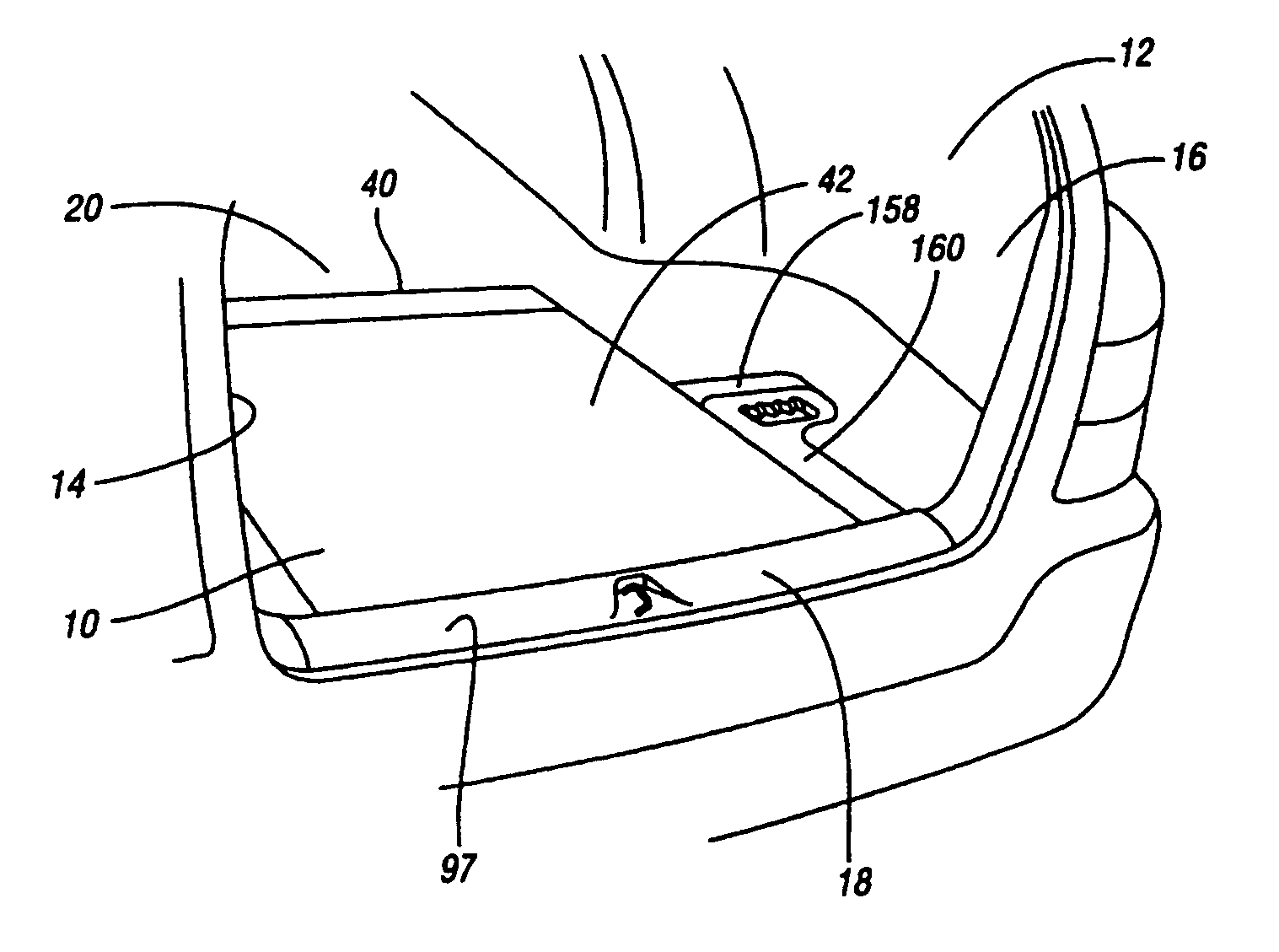
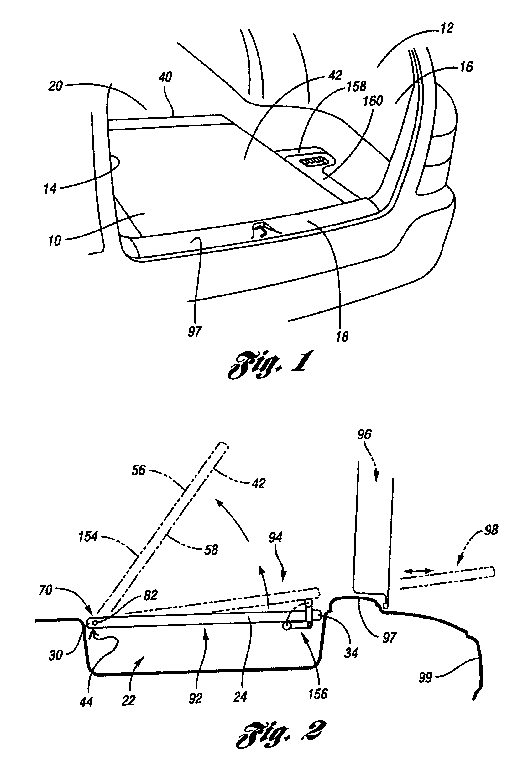
[0017]In FIG. 1, the rear cargo area 12 includes a pair of opposing side portions or quarter trim panels 14, 16 that extend longitudinally in relation to the length of the vehicle, a pair of opposing transverse portions 18, 20 that extend laterally, and a storage bin 22 (FIG. 2) positioned between and at a level below the plane of the side and transverse portions.

[0018]The sliding load floor system 10 disclosed herein includes a slide mechanism 24 (FIG. 2), or other linear bearing or linear motion system. The slide mechanism 24 has a pair of opposing rail members coincident with the floor 42. Each rail member has a forward edge 30 and a rearward edge 34. Optionally, a frame (not shown) is slidably received by the slide mechanism. Preferably, the frame ca...


PUM


Abstract

A sliding load floor system for use in the rear cargo area of a vehicle. The cargo area has a pair of opposing side portions that extend longitudinally in relation to the center line of the vehicle. A pair of opposing transverse portions extend laterally in relation to the vehicle. A storage area is positioned between and at a level below a plane including the side and transverse portions. The sliding load floor system comprises a slide mechanism including a pair of opposing rail members having a forward edge, and a removable load floor that is detachably positioned in relation to the slide mechanism; and a hinge assembly that is mounted to the side portions. The forward edges of the rail members are connected to the hinge assembly so that the slide mechanism, and the removable load floor may be moved arcuately in relation to the hinge assembly, and the load floor slid rearwardly. Also included is a levitation mechanism for raising a rear edge of the sliding load floor so that the load floor may be extended rearwardly outside the vehicle across a raised sill in the cargo area.

Description

BACKGROUND OF THE INVENTION[0001]1. Field of the Invention[0002]The invention relates to a sliding load floor system for the cargo area of a vehicle to allow ergonomic loading and unloading of heavy cargo.[0003]2. Background Art[0004]Today's roads are traveled by full-size pickup trucks, mid-size, and compact vehicles. Typically, they have relatively short rear cargo areas. Abbreviated length restricts the ability of the vehicle operator who wishes to ergonomically transport longer or heavier items that would otherwise be accommodated by vehicles having a longer bed. Tailgate extension devices offer an extended bed floor area. See, e.g., U.S. Pat. Nos. 4,023,850; 4,531,773; and 5,755,480.[0005]To access the rear cargo area, one must first, for example, raise a tailgate or open the rear doors. To retrieve a heavy package located forwardly in the rear cargo area, one must reach over the rear fascia (or rear bumper) area of the vehicle. This may be inconvenient for cleanliness reasons ...

Claims


Application Information

Patent Timeline
Patent Type & Authority Patents(United States)
IPC IPC(8): B60P3/34
CPCB60R5/041
Inventor STURT, ALANDLUGOSZ, ARTUR W.
Owner INT AUTOMOTIVE COMPONENTS GRP NORTH AMERICA INC
Why Eureka
Try Eureka