External thin-wall vacuum duct maglev traffic system of power system

A vacuum pipeline and power system technology, applied in sliding/floating railway systems, tunnel systems, tracks, etc., can solve problems such as increasing pipeline wall loads, occupying effective pipeline space, and heat accumulation in pipelines

Inactive Publication Date: 2010-09-22
张耀平
View PDF15 Cites 35 Cited by
  • Summary
  • Abstract
  • Description
  • Claims
  • Application Information

AI Technical Summary

Problems solved by technology

[0005] (1) Installing linear motors and suspension mechanisms in the pipeline will cause great trouble and difficulty to the construction. If the section of the pipeline is small, such as less than 3m, it will It is almost impossible to carry out manual and mechanical work in the pipeline;
[0006] (2) Linear motors and suspension mechanisms are the main heat sources during the operation of vacuum pipeline transportation, which will lead to heat accumulation in the pipeline and affect the normal running and operation safety of the train;
[0008] (4) The linear motor and suspension mechanism occupy the effective space in the pipeline, increase the load on the pipeline wall, and increase the construction cost of the vacuum pipeline

Method used


Image

  • External thin-wall vacuum duct maglev traffic system of power system
  • External thin-wall vacuum duct maglev traffic system of power system
  • External thin-wall vacuum duct maglev traffic system of power system

Examples


Embodiment approach 1

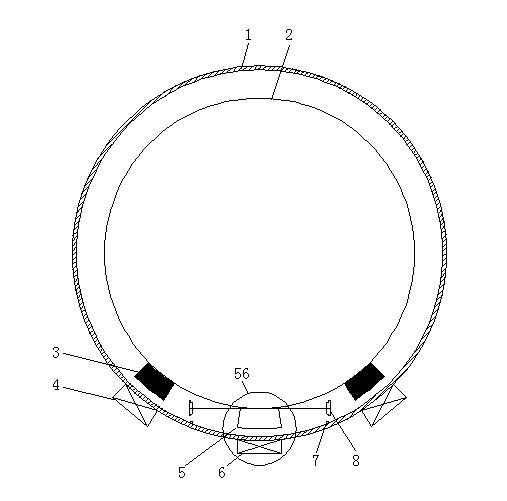
[0025] For repulsive levitation, electric levitation and high temperature superconducting magnetic levitation, the layout of linear motor and levitation system can be adopted as figure 1 structure shown. For example, when high-temperature superconducting maglev is used, the vehicle-mounted levitation mechanism (3) is a low-temperature Dewar containing superconducting blocks and liquid nitrogen, and the levitation mechanism (4) fixed outside the tube wall is a permanent magnet guide rail.

[0026] The support wheels (8) and rails that provide support and walking for the vehicle (2) can also be arranged on both sides of the lower half of the vehicle / pipe, such as Figure 4 shown.

[0027] The linear motor can also be arranged on the top, that is, the mover (3) is installed on the top of the vehicle, and the stator (4) is installed on the top of the pipe, such as Figure 5 shown.

Embodiment approach 2

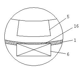
[0029] For suction suspension, the suspension mechanism should be set near the top of the vehicle (2) and pipeline (1), such as Figure 6 shown.

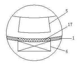
[0030] It is also possible to adopt a mixed suspension method, arrange the suspension mechanism that provides repulsion at the bottom, and arrange the suspension mechanism that provides suction at the top, such as Figure 7 shown. Figure 7 Middle (65) can be linear motor, also can be suspension mechanism.

Embodiment approach 3

[0032] The superconducting maglev vehicle of the Yamanashi test line in Japan belongs to electric suspension, and the suspension and driving devices are on both sides of the vehicle and the line. For this suspension mode, it is enough to arrange the suspension mechanism and the drive mechanism on both sides of the vehicle and the pipeline accordingly. Such as Figure 8 As shown, the vehicle-mounted suspension mechanism and the driving mechanism (11) are arranged on both sides of the vehicle (2), and the suspension mechanism and the driving mechanism (12) fixed on the pipeline are arranged outside the pipeline wall.

[0033] In this suspension mode, the pipeline can also be designed as an arch, such as Figure 9 shown. Figure 9 Middle (18) is the vehicle-mounted suspension and drive device / linear motor, and (19) is the fixed suspension and drive device / linear motor belonging to the track component. The pipe wall at the place where the suspension and driving device (19) is ins...


PUM


Abstract

The invention provides an external thin-wall vacuum duct maglev traffic system of a power system. A vacuum duct with small wall thickness is adopted, a linear motor coil, a track levitation mechanism and other communication, detecting and control devices are arranged outside the duct and provide power, levitation force and control to vehicles in the duct in the state that one thin duct wall is used for separation. The material of the duct wall is required to have no effect on the electromagnetic field of a linear motor and the levitation magnetic field of a levitation device, for example, non-magnetized stainless steel, carbon alloy, glass fiber reinforced plastics or high-strength organic materials are adopted, or the duct is made of a composite material. The arrangement has the advantages that the installation construction of a linear motor stator and the levitation mechanism can be conveniently performed outside the duct; routine maintenance and repair during operation can also be performed outside the duct; mechatronic systems can be well cooled, and heat aggregation in the vacuum duct is avoided; and the space in the duct is not occupied; and the construction, maintenance and system operation costs of the vacuum duct high-speed maglev traffic system can be lowered.

Description

technical field [0001] The invention relates to the layout of a linear motor, a magnetic levitation system and a track facility in a vacuum pipeline maglev transportation system, and belongs to the technical field of combining the power system arrangement of the vacuum pipeline transportation with pipeline structure technology. Background technique [0002] Vacuum pipeline high-speed maglev transportation is to let the maglev train run in the vacuumed pipeline, and the speed can reach 600km / h or even 6000km / h or more. Its basic components include: vacuum pipeline, maglev vehicle, linear motor and operation control equipment. The on-board parts matched with the linear motor and the on-board equipment matched with the suspension system must be installed on the car, while some power equipment fixed on the track or pipeline can be placed inside or outside the pipeline. When these power equipment or detection and control systems are arranged in the pipeline, since the inside of ...

Claims


Application Information

Patent Timeline
Patent Type & Authority Applications(China)
IPC IPC(8): B61B13/10B61B13/08B60L13/04
CPCY02T90/16
Inventor 张耀平李胜善丁铁骑郭翔鹤梁静周君
Owner 张耀平
Why Eureka
Try Eureka