Retroreflective sheeting having high retroreflectance at low observation angles

a technology of observation angle and retroreflective sheeting, which is applied in the field of retroreflective sheeting, can solve the problems of low retroreflective efficiency of microsphere-based sheeting, low sensitivity to orientation, and impracticality of making small cube corner elements. achieve the effect of improving retroreflective properties

Inactive Publication Date: 2007-03-13
3M INNOVATIVE PROPERTIES CO
View PDF48 Cites 76 Cited by
  • Summary
  • Abstract
  • Description
  • Claims
  • Application Information

AI Technical Summary

Benefits of technology

[0017]Described herein is retroreflective sheeting comprising an array of cube corner elements. The sheeting provides improved retroreflective properties as can be described with one or more fractional retroreflectance properties (i.e. at an entrance angle of −4 degrees). In one aspect, the fractional retroreflectance of the sheeting is at least 20% at an observation angle of 0.5. In another aspect, the fractional retoreflectance of the sheeting is at least 35% at an observation angle of 1.0. In another aspect, the fractional retroreflectance is at least 40% / degree at an observation angle of 2.0. In another aspect, the fractional retroreflectance slope of the sheeting is at least 25% / degree at observation angles ranging from 0.2 to 0.5. In yet another aspect, the sheeting exhibits a fractional retroreflectance slope of at least 25% / degree at an observation angle of 0.2 and a fractional reflectance slope of at least 10% / degree for an observation angle of 1.0. The retroreflective sheeting may have any combination of such fractional retroreflectance properties as well.

Problems solved by technology

Thus, such microsphere-based sheeting has a relatively low sensitivity to the orientation at which the sheeting is placed on a surface.
In general, however, such sheeting has a lower retroreflective efficiency than cube corner sheeting.
However, such techniques are impractical for making small cube corner elements (e.g. those having a cube height less than about 1 millimeter) because of the large number of pins and the diminishing size thereof required to be precisely machined and then arranged in a bundle to form the mold.
A drawback to direct machining techniques, however, has been reduced design flexibility in the types of cube corner geometries that can be produced, which in turn affects the total light return.
However, techniques employing laminae have less design flexibility in comparison to that achievable by pin bundling.
However, it is difficult to maintain geometric accuracy with this multi-step fabrication process.
Design constraints may also be evident in the resulting PG cube corner elements and / or arrangement of elements.
Tiling can be visually objectionable.
Further, tiling increases the number of manufacturing steps in making the tooling employed for manufacture of the sheeting.

Method used


Image

  • Retroreflective sheeting having high retroreflectance at low observation angles
  • Retroreflective sheeting having high retroreflectance at low observation angles
  • Retroreflective sheeting having high retroreflectance at low observation angles

Examples


examples 1a and 1b

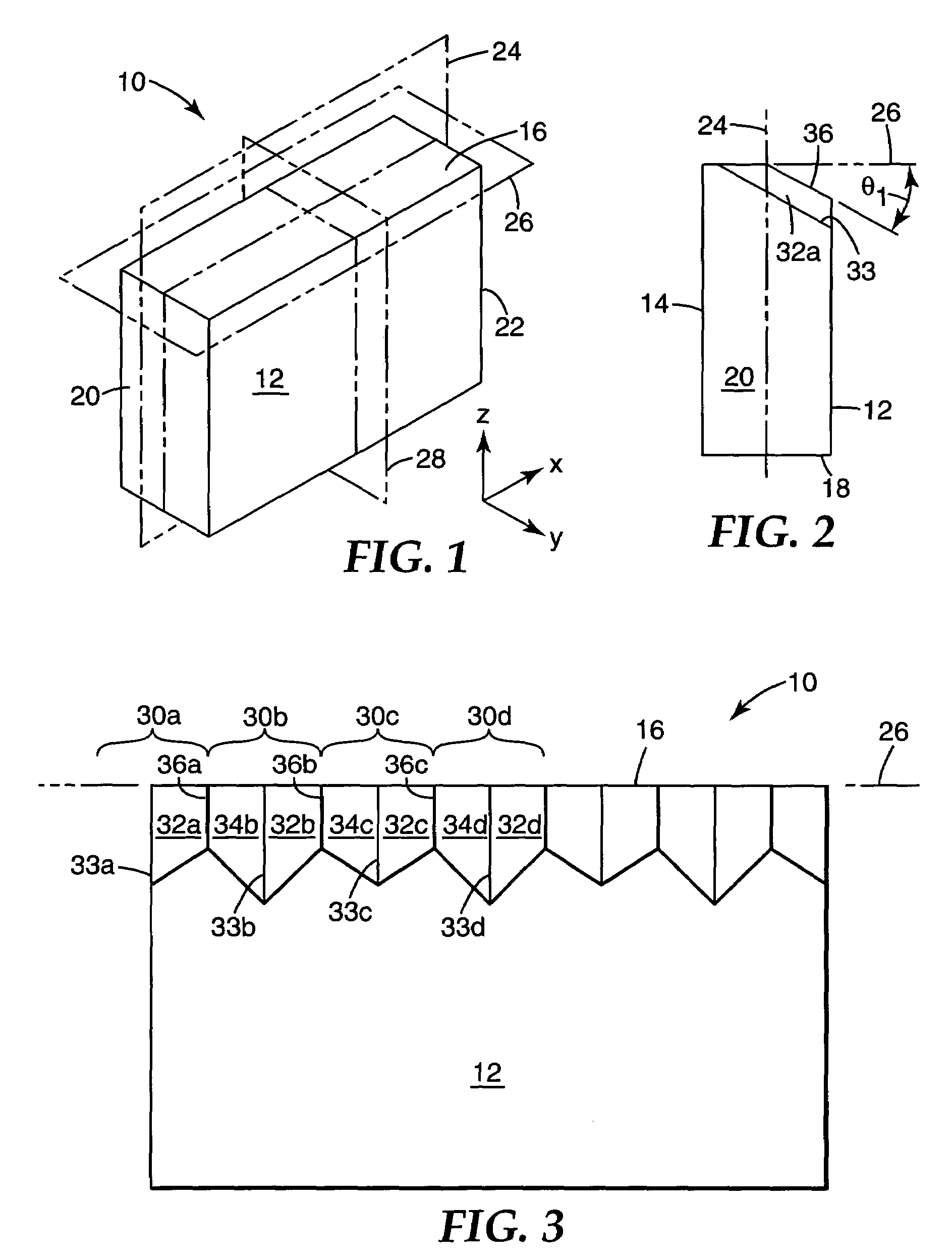
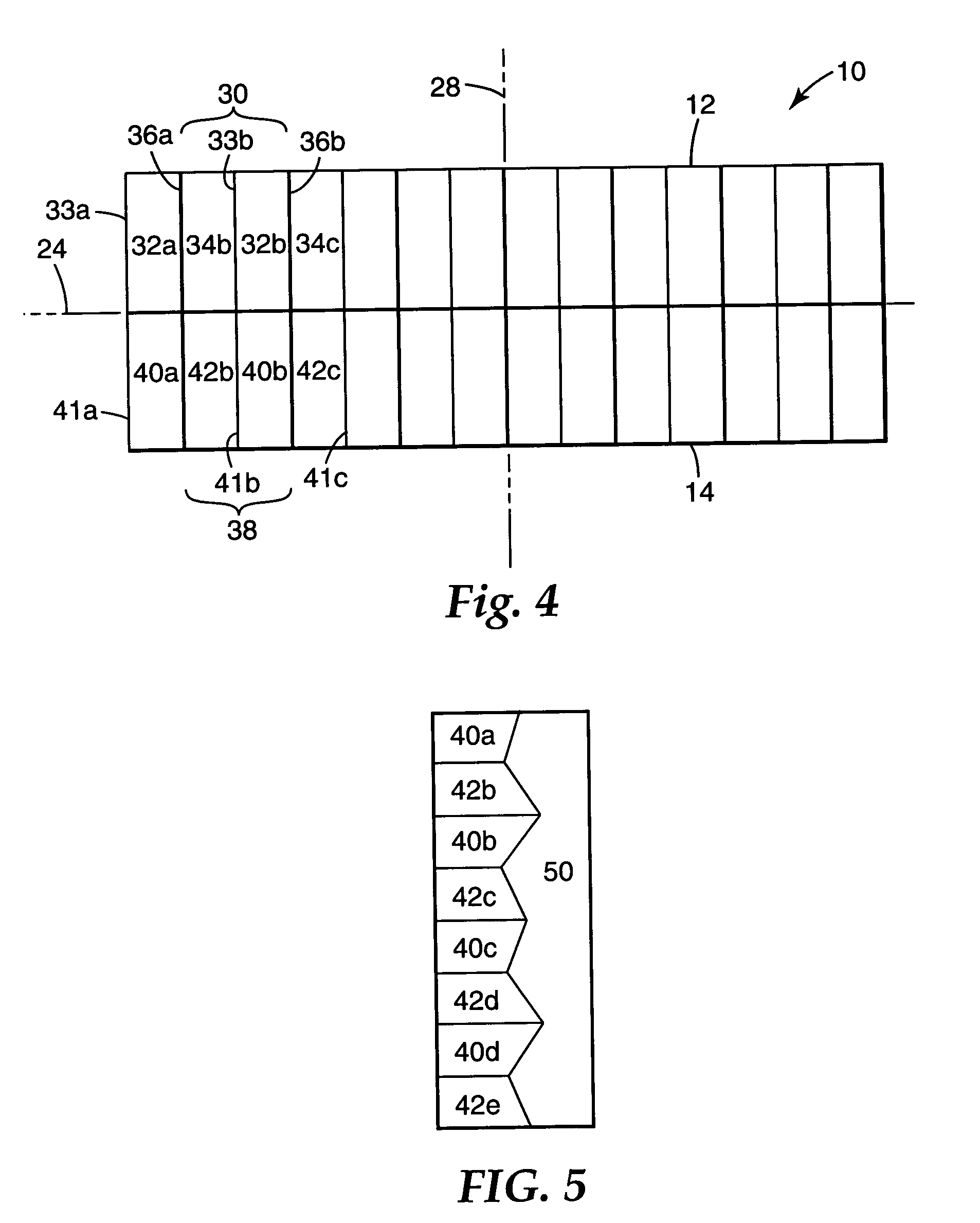
[0157]Grooves were formed in individual lamina, the individual lamina assembled, and the microstructured surface replicated as described in previously cited U.S. Patent Application Publication No. 04-0175541-A1. U.S. Patent Application Publication No. 04-0175541-A1 was filed concurrently with Provisional Patent Application Ser. No. 60 / 452,464 to which the present application claims priority. All the machined laminae had the geometry depicted in FIGS. 6 and 7, with slight variations due to varying the half angle error, skew and inclination of the side grooves. The lamina thickness was 0.0075 inches (0.1905 mm) and the side groove spacing was 0.005625 inches (0.1428 mm) except for the slight variations just described. A repeating pattern of eight cubes was sequentially formed on each lamina. This repeating pattern of cubes was formed by varying the half angle errors, skew, and inclination of the side grooves as set forth in forthcoming Tables 10–14. Each row in the tables defines the ...


PUM

PropertyMeasurementUnit
fractional reflectanceaaaaaaaaaa

Abstract

The present invention relates to retroreflective sheeting.

Description

RELATED APPLICATIONS[0001]This application is a continuation-in-part of U.S. patent application Ser. Nos. 10 / 404,890 and 10 / 404,265, concurrently filed Apr. 1, 2003, which each claim priority to provisional U.S. Patent Application Ser. No. 60 / 452,464 filed Mar. 6, 2003.FIELD OF THE INVENTION[0002]The present invention is directed to retroreflective sheeting.BACKGROUND OF THE INVENTION[0003]Retroreflective materials are characterized by the ability to redirect light incident on the material back toward the originating light source. This property has led to the widespread use of retroreflective sheeting for a variety of traffic and personal safety uses. Retroreflective sheeting is commonly employed in a variety of articles, for example, road signs, barricades, license plates, pavement markers and marking tape, as well as retroreflective tapes for vehicles and clothing.[0004]Two known types of retroreflective sheeting are microsphere-based sheeting and cube corner sheeting. Microsphere...

Claims


Application Information

Patent Timeline
Patent Type & Authority Patents(United States)
IPC IPC(8): G02B5/122B29D11/00G02B5/124
CPCG02B5/124B29D11/00605G02B5/12
Inventor SMITH, KENNETH L.
Owner 3M INNOVATIVE PROPERTIES CO
Why Eureka
Try Eureka