
Safety razor

a safety razor and blade technology, applied in the field of safety razors, can solve the problems of increasing costs, difficult to separate manufacture several supporting structure parts, and difficult to fix a plurality of blades at spaces, and achieve the effect of efficient ejecting moustache, surely and simply fixed, and easy insertion

Inactive Publication Date: 2007-03-20
KAI R&D CENT CO LTD
View PDF28 Cites 37 Cited by
  • Summary
  • Abstract
  • Description
  • Claims
  • Application Information

AI Technical Summary

Benefits of technology

[0020]With the invention constituted in the above-mentioned manner, the blade support parts are held to the non-overlapping portions of the blades to thereby support the respective blade bodies apart from one another. That is, instead of fixing blades integrally in slots by means of injection molding, the blade support parts are held to the non-overlapping portions of the blades to support the blades, so that mechanical assembly of support structure parts is made possible. Accordingly, metal molds are not so much complicated and it is not necessary to fix blade bodies to perform injection molding, so that manufacture is simple and inexpensive as compared with conventional products. Also, degradation in yield is eliminated.
[0021]According to one aspect of the present invention, projections themselves projecting from a bottom surface of a roof plate can be inserted through holes of the respective blades and holes of a blade base in order to interpose the blades between the blade base and the roof plate support those blades, which are disposed below an upper blade. Accordingly, even when blade body supports and blade base inserts are not formed separately, the projections serve as both parts to produce an effect that the constitution is made simple and cost is reduced.
[0022]According to one exemplary embodiment, the number of steps provided on the projections to support those blades, which are disposed below the upper blade, corresponds to the number of blades minus 1. Accordingly, all blades disposed below the upper blade are supported by the respective steps, so that it is possible to stably support the blades.
[0024]As described above, in recent years, with a safety razor having a plurality of blades, respective blade bodies are partially fixed midway in order to efficiently eject moustache refuse, which has been clogged between the blades, rearward, and spaces between blade bodies are retained. Therefore, there is a fear that blade bodies bend at unfixed portions thereof. According to one embodiment, a safety razor includes a plurality of blades mounted at predetermined spaces on a head and an insert spacer inserted between the blades from a rear end opening of the head to be fixed. Accordingly, the respective blades can be surely and simply fixed by manufacturing an insert spacer and mounting the same on a safety razor.
[0025]At least one of the vertically adjacent insert pieces is laterally provided in plural, and the insert pieces vertically adjacent to the ones are alternately arranged laterally. Accordingly, the insert pieces can be easily inserted into the head as compared with the case where vertically adjacent insert pieces fully overlap each other.

Problems solved by technology

In this manner, with the support structure, in which blades are fixed by means of slots, it is difficult to separately manufacture several support structure parts to mechanically assemble them, so that the whole support structure together with blades is molded by fixing the blades in predetermined positions and injection molding plastics.
However, there is a disadvantage that metal molds used in injection molding to manufacture a whole cartridge replaceable blade in a body are very complicated to lead to an increase in cost.
Also, it is not easy to fix a plurality of blades at spaces at the time of injection molding, which incurs a fear of bad yield.
Therefore, there is a fear that blade bodies bend at unfixed portions thereof.
Also, when a safety razor having a plurality of blades is assembled, the blades are stacked on one another, but the stacked blades can be shifted relative to one another due to vibrations prior to fixation of the blades, which leads to a bad yield.

Method used


Image

  • Safety razor
  • Safety razor
  • Safety razor

Examples


Embodiment Construction

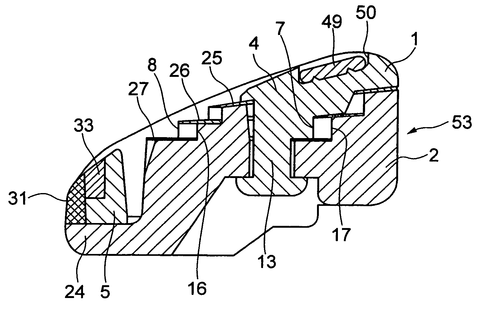
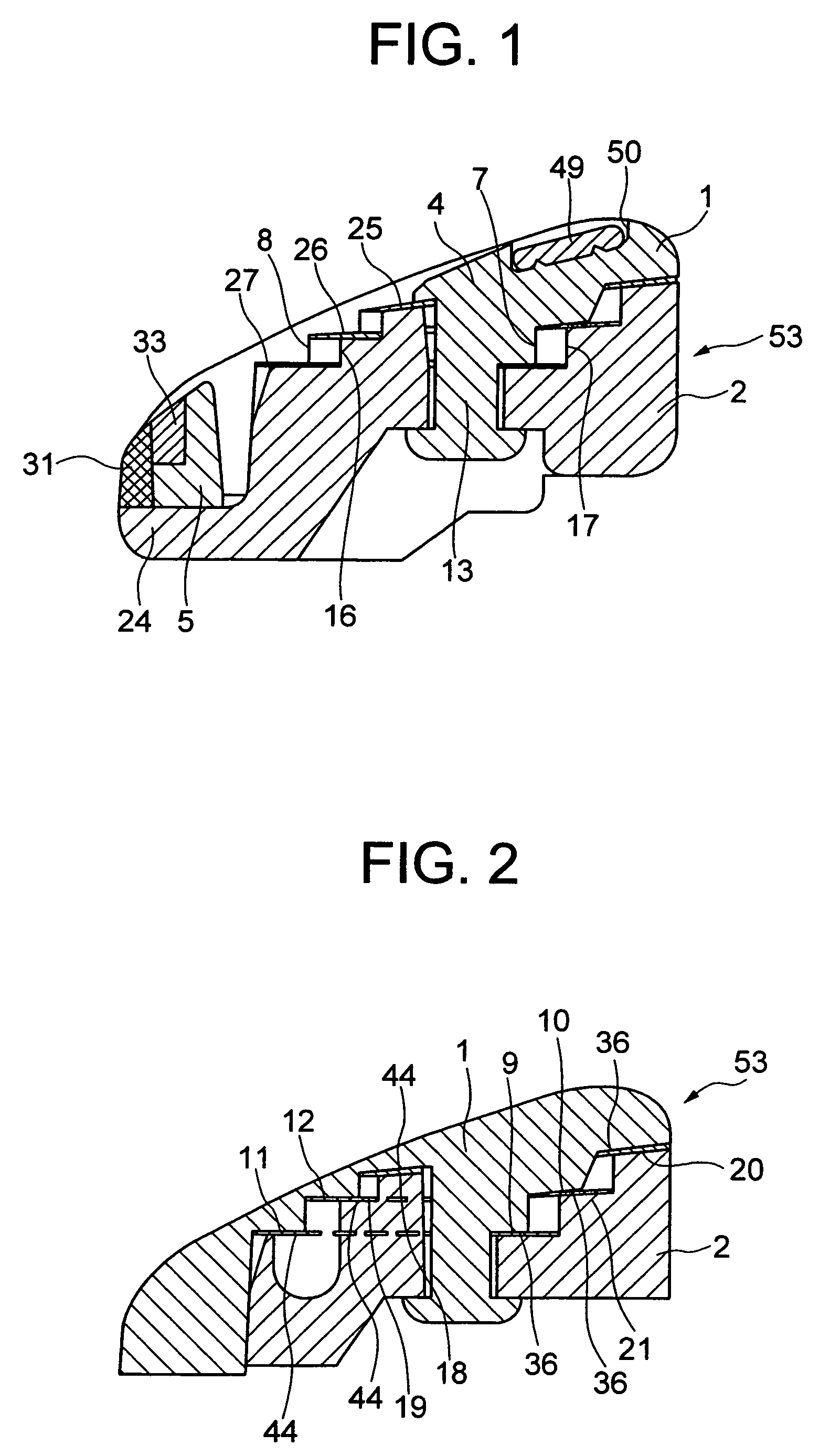
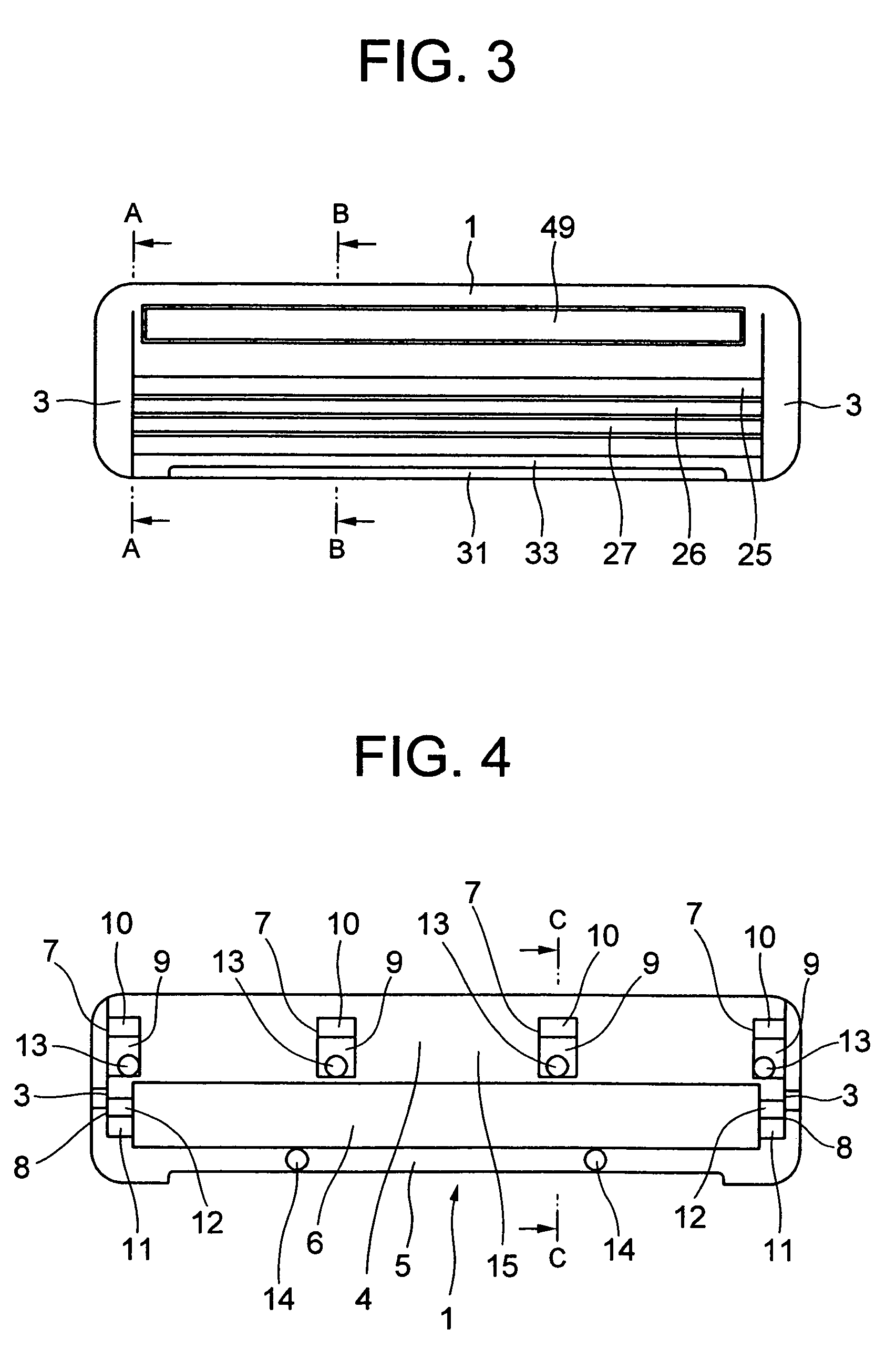
[0057]Embodiments of the invention will be described below with reference to the drawings. The drawings show a cartridge replaceable blade having three blades, the cartridge replaceable blade corresponding to a head 53 of a safety razor, and a support structure for blades comprising a roof plate 1 and a blade base 2. The roof plate 1 comprises a blade pressure foot 4 between both side portions 3, 3, and a guard body 5 extending between both front ends of the both side portions 3, 3 and interposing an opening 6 between it and the blade pressure foot 4. Edges of the blades are exposed from the opening 6. Also, a shaving aid 49 is fixed in a recess 50 provided on an upper surface of the blade pressure foot 4. Since two ridges are provided on a bottom of the recess 50, the shaving aid 49 is firmly fixed. Of course, the invention is not limited to cartridge replaceable blades but may be applied to safety razors, in which a blade base and a handle are integrally formed.

[0058]As shown in F...


PUM


Abstract

A safety razor with a plurality of blades comprising a head provided with a plurality of vertically adjacent blades, which do not wholly overlap one another, and blade support parts supporting the respective blades apart from one another in order to retain the respective blades at spaces, and wherein non-overlapping portions, which do not overlap one another, are formed on supported portions of the respective blades and the blade support parts are held to the non-overlapping portions of the blades to support the blades. A support structure can be divided into two members to be manufactured and mechanically assembled, metal molds are not so much complicated, and mechanical assembly of blades is made possible to prevent degradation in yield.

Description

TECHNICAL FIELD[0001]The present invention relates to a safety razor having a plurality of blades, and more particular, to a structure, in which respective blades are supported at spaces.BACKGROUND ART[0002]A safety razor having a plurality of blades suffers from accumulation of moustache refuse, cream, or the like between blades in use, and so a safety razor intended for efficient removal of these has been proposed. JP-A-2000-308771 discloses a support structure, in which a plurality of blades are supported at spaces. This support structure comprises a plurality of blades and a frame supporting the plurality of blades, a plurality of vertical ribs are arranged between opened rear portions of the frame, and the ribs comprise slots, which are different in level and in which rear edges of the blades are mounted.[0003]A conventional support structure is configured in the above-mentioned manner such that rear edges of the blades are mounted in the slots provided on the ribs. In this man...

Claims


Application Information

Patent Timeline
IPC IPC(8): B26B21/00B26B21/02B26B21/22
CPCB26B21/222B26B21/22B26B21/4012
Inventor MIYAZAKI, HIROAKINAKASUKA, HIROYUKI
Owner KAI R&D CENT CO LTD
Learn More