Pedal support structure for a vehicle

a technology for supporting structures and vehicles, applied in mechanical control devices, instruments, tractors, etc., can solve problems such as the deformation of the toeboard panel 3/b>, and achieve the effect of avoiding the imposing of an impact load

Inactive Publication Date: 2007-03-20
SUBARU CORP
View PDF15 Cites 8 Cited by
  • Summary
  • Abstract
  • Description
  • Claims
  • Application Information

AI Technical Summary

Benefits of technology

[0006]It is a primary object of the present invention to provide a support structure of a pedal for protecting a driver. This improvement is realized by separating the pedal away from feet of driver in case of a car crash where a bulkhead and a toeboard panel intrude into a passenger compartment. The separation prevents the pedal from hitting the driver at the feet, and avoids imposing an impact load of the crash on the feet of driver.

Problems solved by technology

However, with the conventional support structure for the pedal, a car crash might cause the bulkhead 2 and the toeboard panel 3 to deform to intrude into a passenger compartment 5.

Method used


Image

  • Pedal support structure for a vehicle
  • Pedal support structure for a vehicle
  • Pedal support structure for a vehicle

Examples


Embodiment Construction

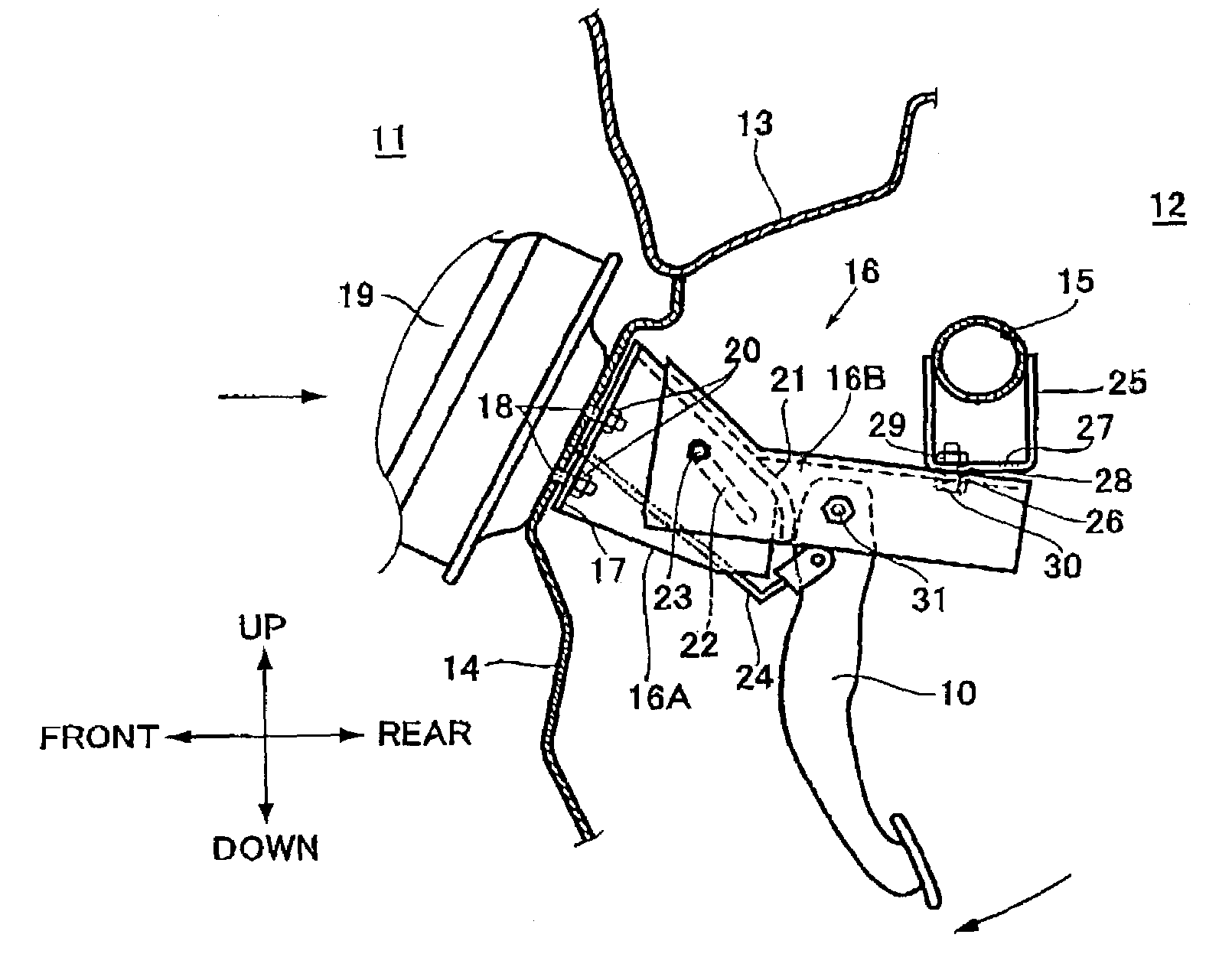
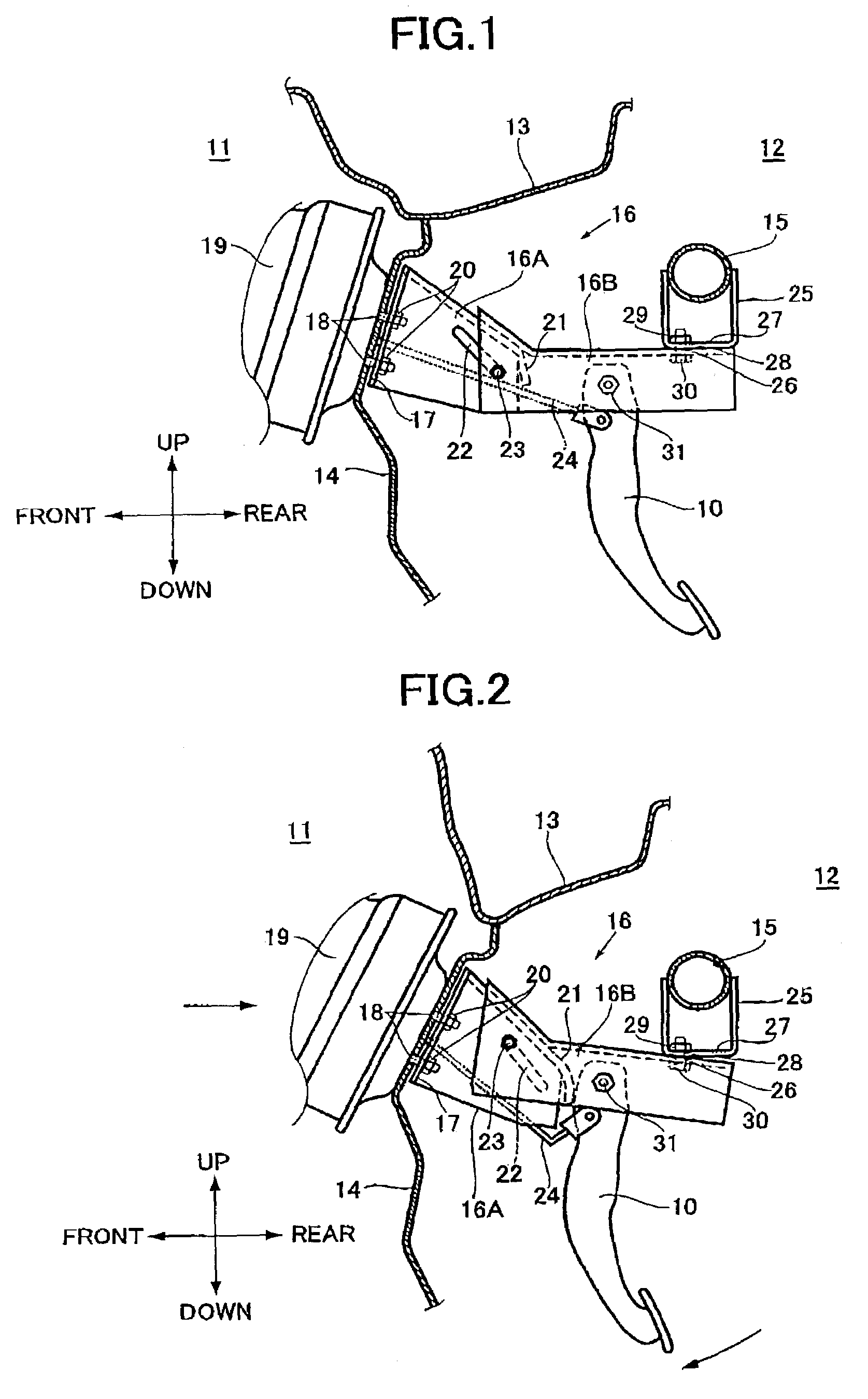
[0018]Preferred embodiments of the present invention, presently considered to be the best mode, is hereinafter described in detail with reference to FIG.1. FIG. 1 illustrates an example according to the embodiment when the present invention is applied to a support structure of a brake pedal.

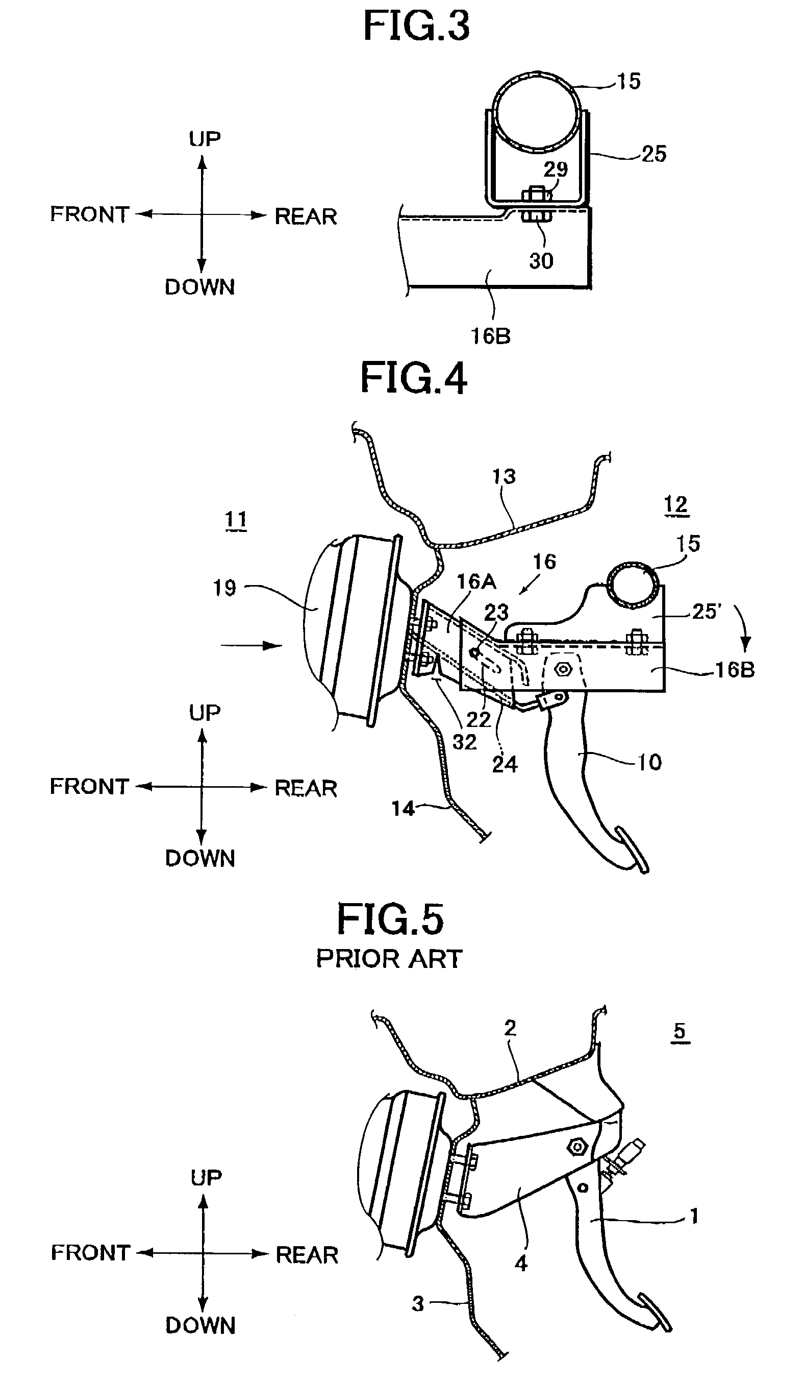
[0019]As shown in FIG. 1, there are disposed a bulkhead 13 and a toeboard panel 14, as a partition wall for separating an engine compartment from a passenger compartment, in a recess below an instrument panel (not shown) where a brake pedal 10 is located. There is also disposed a steering beam 15 along a lateral direction of a vehicle body in the recess below the instrument panel. The steering beam 15, as a rigidly reinforced member, secures the instrument panel and supports steering components in order to avoid being displaced in case of a crash. The brake pedal 10 is supported by the vehicle body via a pedal bracket 16. The pedal bracket 16 is fixed to a toeboard panel 14 at a front end part of...


PUM


Abstract

A support structure for supporting a pedal for a vehicle with a pedal bracket connected to a toeboard panel for separating an engine compartment from a passenger compartment and to a steering beam disposed at a backward position from the toeboard panel. The support structure has a front bracket section of the pedal bracket fixed to the toeboard panel, and a rear bracket section of the pedal bracket fixed to the steering beam through a support bracket for the steering beam, the pedal being attached directly to the rear bracket section, wherein a rear end part of the front bracket section is slidably secured into a front end part of the rear bracket section with coupler.

Description

BACKGROUND OF THE INVENTION[0001]The present invention relates to a pedal support structure for a vehicle, more specifically to the support structure for a pedal intended for improving safety in case of a car crash.[0002]The present application claims priority from Japanese Patent Application No. 2002-162931, the disclosure of which is incorporated herein by reference.[0003]Conventionally, such a suspension-type pedal as a brake or clutch pedal is located at a recess below an instrument panel for converting an operational force into a liquid pressure to apply a braking force and to disengage a friction clutch. Such a pedal 1, as shown in FIG. 5, is supported by a car body via a pedal bracket 4. The pedal bracket 4 is fixed to a bulkhead 2 at a top end part of the same pedal bracket 4, and to a toeboard panel 3 at a front end part thereof.[0004]However, with the conventional support structure for the pedal, a car crash might cause the bulkhead 2 and the toeboard panel 3 to deform to ...

Claims


Application Information

Patent Timeline
Patent Type & Authority Patents(United States)
IPC IPC(8): G05G1/30B62D25/08B60R21/09B60T7/06G05G1/32
CPCB60R21/09B60T7/065G05G1/323G05G1/32Y10T74/20888Y10T74/20528
Inventor SANDO, MASAHIRO
Owner SUBARU CORP
Why Eureka
Try Eureka