
Device for testing axial bearing capacity of conical dynamic-pressure spiral groove bearing

A test device and load-carrying capacity technology, which is applied in the direction of mechanical bearing testing, etc., to achieve the effects of simple testing, solving impact loads, and reducing system vibration

Active Publication Date: 2013-10-02
SOUTHEAST UNIV
View PDF8 Cites 4 Cited by
  • Summary
  • Abstract
  • Description
  • Claims
  • Application Information

AI Technical Summary

Problems solved by technology

[0008] Technical problem: Aiming at the problems existing in the current load-carrying capacity test device for conical dynamic pressure spiral groove bearings, this invention proposes a simple test device for the axial load capacity of conical dynamic pressure spiral groove bearings, aiming at simplifying the structure of the test device and reducing costs , Simplify operation and improve work performance

Method used


Image

  • Device for testing axial bearing capacity of conical dynamic-pressure spiral groove bearing

Examples


Embodiment Construction

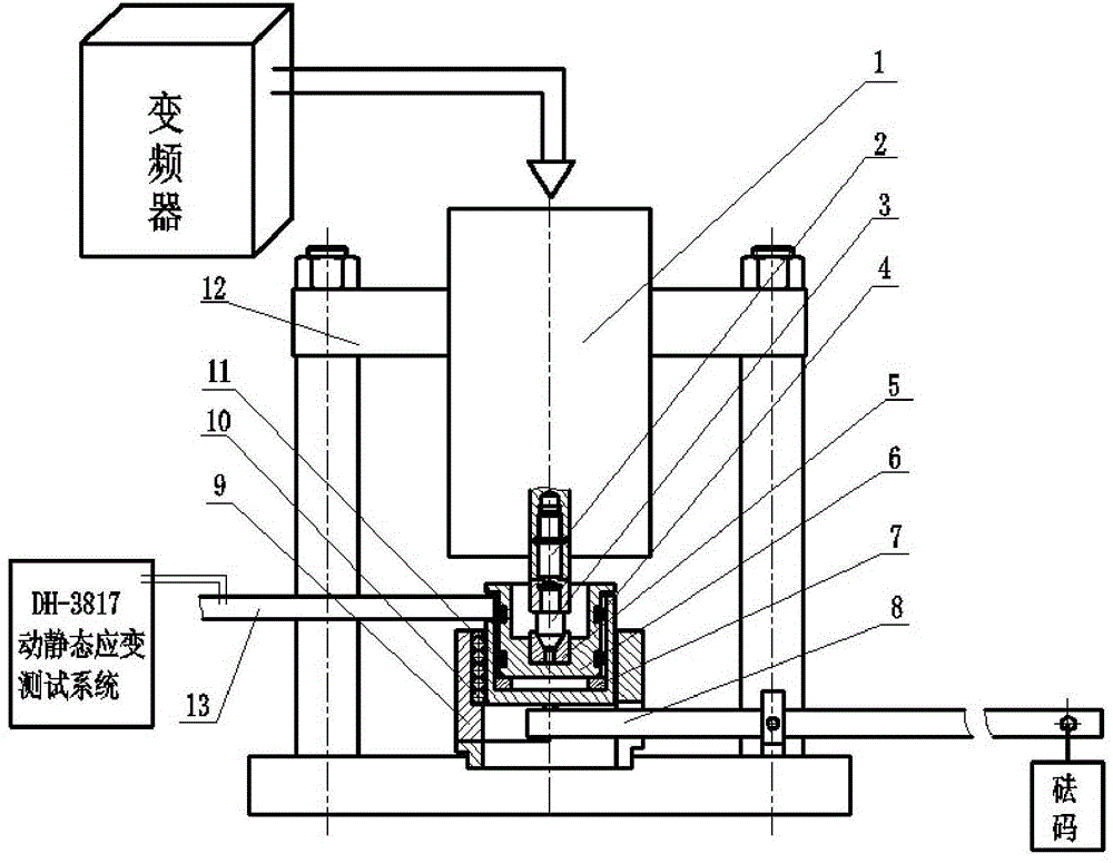
[0018] Structurally, the test device for the axial bearing capacity of the conical dynamic pressure spiral groove bearing consists of a mechanical part and an electric control part. The mechanical part includes: test device frame, transmission shaft, bearing seat ring, washer, damping ring, loading sleeve, split positioning ring, ball, loading lever, strain beam; the electronic control part includes: frequency converter, high frequency motor, Dynamic and static strain gauges.

[0019] The high-frequency motor is installed on the upper part of the test device frame, connected with the frequency converter, and the test bearing is connected with the motor shaft. The test housing is located inside the bearing race. The bearing race is located under the drive shaft and fits inside the damping ring. The damping ring is located between the bearing load sleeve and the bearing race. A U-shaped groove is opened in the loading sleeve, and the strain beam is embedded in it. The gasket...


PUM


Abstract

The invention discloses a device for testing axial bearing capacity of a conical dynamic-pressure spiral groove bearing. The device for testing the axial bearing capacity of the conical dynamic-pressure spiral groove bearing consists of a mechanical part and an electrical control part; a high-frequency motor (1) is mounted at the upper part of a test device frame (12); a transmission shaft (2) is mounted at the lower part of the high-frequency motor; a tested bearing (3) is mounted below the transmission shaft; a bearing base (5) is mounted inside a bearing race (6); the bearing race is positioned inside a loading sleeve (11) at the upper part of a gasket (4); the loading sleeve is mounted inside a split positioning ring (9); a ball (10) is mounted inside a rectilinear runner of the split positioning ring; the split positioning ring is mounted at the bottom of the test device frame (12); a loading lever (8) is mounted at the bottom of the test device frame (12); a weight is arranged at the outer end of the loading lever; the inner end of the loading lever is arranged below the loading sleeve; the inner end of a strain beam (13) is embedded into a U-shaped groove of the loading sleeve; the outer end of the strain beam is connected with a dynamic and static strain testing system of the electrical control part.

Description

technical field [0001] The invention relates to a test device for the bearing capacity of a conical dynamic pressure spiral groove bearing, which belongs to the field of mechanical engineering (basic components). Background technique [0002] Since the Philips Laboratory in the Netherlands put forward the basic theory of dynamic pressure spiral groove bearings in the 1860s, the dynamic pressure spiral groove bearings have developed rapidly and become an important branch of the field of dynamic pressure sliding bearings. Conical dynamic pressure spiral groove bearing is a special form of this kind of bearing. It uses the dynamic pressure lubricating film formed on the bearing cone surface to provide axial and radial support at the same time. It has compact structure, large load capacity and relatively simple manufacture. Etc. For the first time, the Philips laboratory successfully applied the conical dynamic pressure spiral groove bearing to the shaft of the micro motor, and...

Claims


Application Information

Patent Timeline
Patent Type & Authority Applications(China)
IPC IPC(8): G01M13/04
Inventor 蒋书运马杰
Owner SOUTHEAST UNIV
Learn More