Multi-row cam-actuated centrifugal clutch

a centrifugal clutch and cam-actuated technology, applied in the field of centrifugal clutches, can solve the problems of insufficient centrifugal force generated to clamp the clutch plate together without substantial slipping or withou

Inactive Publication Date: 2003-05-08
DRUSSELL WILFLEY DESIGN LLC
View PDF7 Cites 4 Cited by
  • Summary
  • Abstract
  • Description
  • Claims
  • Application Information

AI Technical Summary

Problems solved by technology

However, in certain applications it was found that there is insufficient centrifugal force generated to clamp the clutch plates together without substantial slipping or without utilizing a larger size case or cover which exceeds the space allowances within stock engine cases.

Method used


Image

  • Multi-row cam-actuated centrifugal clutch
  • Multi-row cam-actuated centrifugal clutch
  • Multi-row cam-actuated centrifugal clutch

Examples


Embodiment Construction

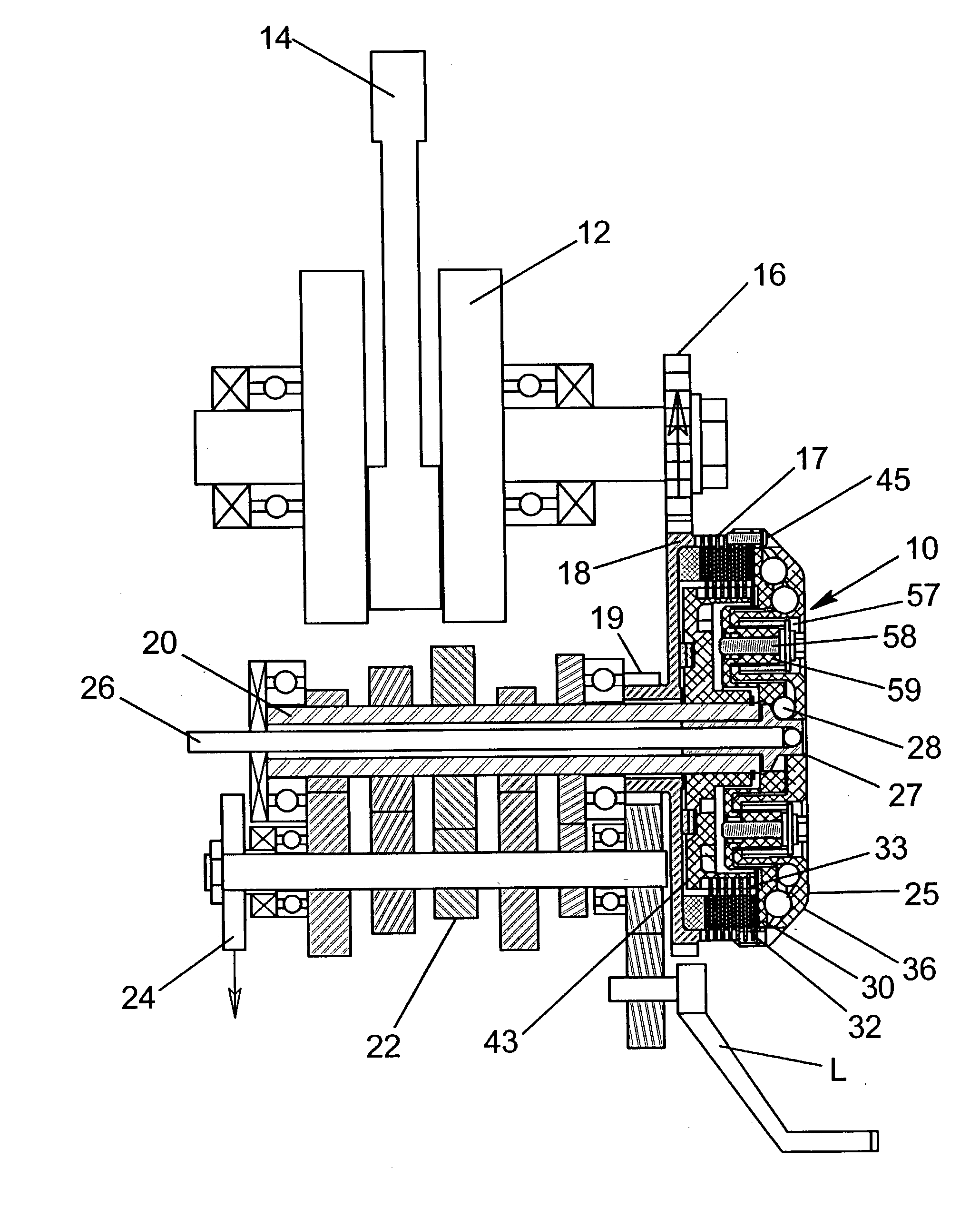
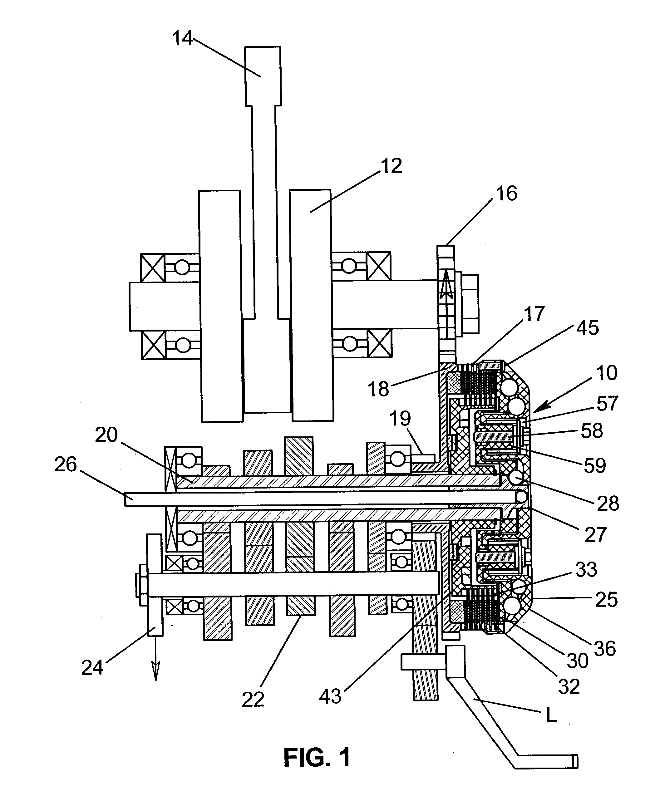
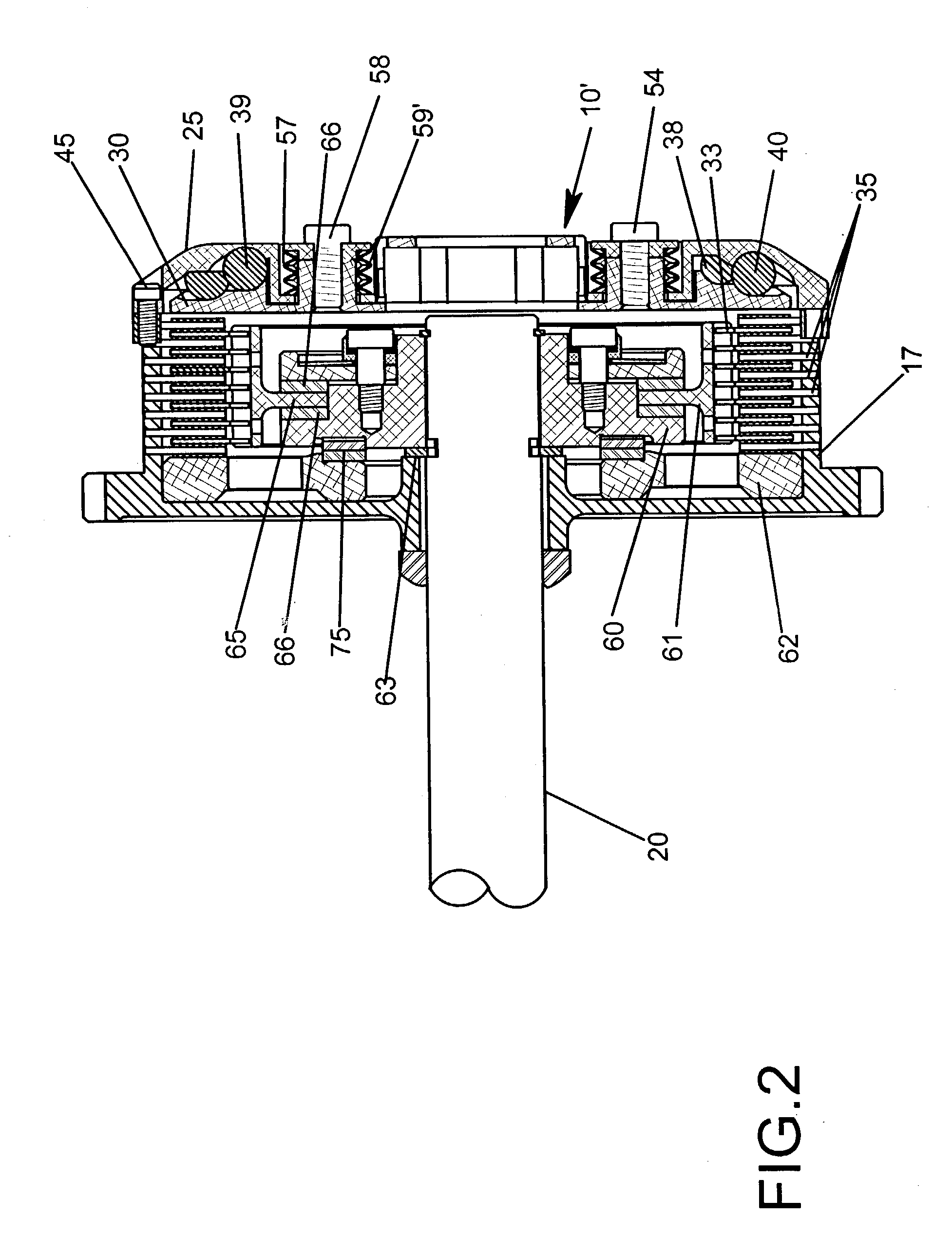
[0031] FIGS. 2 to 11 illustrate a preferred form of clutch 10' in which like parts to those of FIG. 1 are correspondingly enumerated. More specifically, in FIGS. 2 and 3, the manual override mechanism in FIG. 1 consisting of the push rod 26, slide 27 and cams 28 has been removed. Instead, the clutch is actuated only by the cam-actuating mechanism 36 which is broadly comprised of radially inner and outer rows of circumferentially spaced cam members or bails 38, 39 and 40 interposed between a pressure plate 30 and a cover 25. The balls 38 to 40 are responsive to centrifugal force to roil outwardly along radial pockets or cam faces 48, 52 and 56 in the pressure plate 30 and aligned pockets or cam faces 46, 50 and 54 in the cover 25 so as to axially displace the outer frictional clutch plates 32 into locking engagement with the inner clutch plates 34.

[0032] An important feature of the present invention resides in the radially inner and outer rows of cam members or balls 38, 39 and 40. P...


PUM


Abstract

A centrifugal clutch for motorcycles employs a cam-actuating mechanism having multiple rows of centrifugal force-responsive cam members of a selected density and size to force a series of clutch plates into clutching engagement over the shortest possible distance and least possible speed of rotation while assuring ease of positive engagement of the clutch members in response slight increases in speed of rotation. The cam-actuating mechanism can be employed with a manual override mechanism to manually control locking and release of the clutch members as well as utilizing a torque limiter to absorb shock loads without unduly increasing the size of the clutch so that it will readily fit into the space occupied by existing or standard clutch mechanisms.

Description

[0001] This application is a continuation-in-part of patent application Ser. No. 09 / 877,518, filed Jun. 7, 2001 for AUTOMATIC CLUTCH WITH MANUAL OVERRIDE CONTROL MECHANISM by Douglas W. Drussel and George Michael Wilfley and assigned to the assignee of this invention and incorporated by reference herein.BACKGROUND AND FIELD OF INVENTION[0002] This invention relates to centrifugal clutches and more particularly relates to novel and improved centrifugal clutches having high density cam members which are urged outwardly under centrifugal force in order to activate the clutching elements.[0003] Centrifugal clutches have been developed for motorcycles utilizing one or two rows of balls or other cam members which would move outwardly in response to rotation of a drive shaft to cause the clutch plates to move into engagement with one another. However, in certain applications it was found that there is insufficient centrifugal force generated to clamp the clutch plates together without subs...

Claims


Application Information

Patent Timeline
Patent Type & Authority Applications(United States)
IPC IPC(8): F16DF16D23/12F16D43/12
CPCF16D43/12F16D23/12
Inventor DRUSSEL, DOUGLAS W.WILFLEY, GEORGE MICHAEL
Owner DRUSSELL WILFLEY DESIGN LLC
Why Eureka
Try Eureka