Electric screw press

A technology of electric screw and motor, which is applied in the direction of presses, stamping machines, manufacturing tools, etc., and can solve the problems of high manufacturing cost and difficult manufacturing

Inactive Publication Date: 2012-11-28
卢怀亮 +1
View PDF9 Cites 4 Cited by
  • Summary
  • Abstract
  • Description
  • Claims
  • Application Information

AI Technical Summary

Problems solved by technology

It is necessary to prepare a special motor for each type of press machine, so the

Method used


Image

  • Electric screw press
  • Electric screw press
  • Electric screw press

Examples


Example Embodiment

[0031] The present invention will be further described below with reference to the drawings and embodiments.

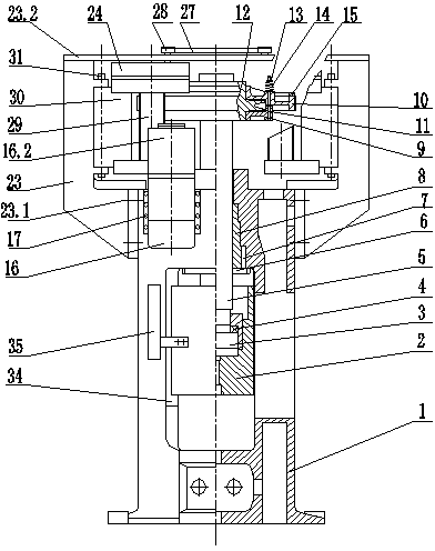
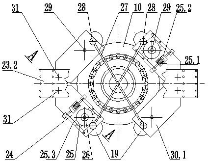
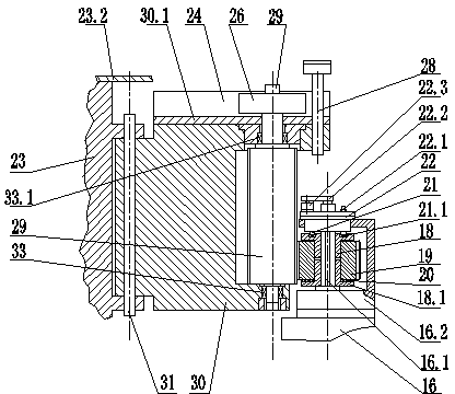
[0032] This embodiment provides an electric screw press, such as figure 1 with figure 2 As shown, it includes a fuselage 1, an even number of motors 16, a screw 5, a slider 2, and an inertia wheel with a large gear 10 on the outer ring. There are four guide rails 34 on the fuselage 1, and the slider 2 can be operated along the guide rail 34 of the fuselage. Reciprocating linear motion. The nut 8 is connected to the body 1 as a whole through the flange 6 and the key 7, and the screw 5 and the nut 8 are threaded. The lower end of the screw 5 is equipped with a thrust bearing 3, and is matched with the slider 2 through the bearing 4. The screw 5 forms a screw pair with the nut 8 to drive the sliding block 2 for linear movement. The disk 9, the large gear 10, the friction block 11, the hub 12, the bolt 13, the spring 14 and the positioning ring 15 are combined to form an ...


PUM


Abstract

The invention relates to the field of mechanical industrial equipment and particularly relates to an electric screw press which comprises a machine body, motors with an even number, a screw rod, a slide block and an inertia wheel with an outer ring as a large gear, wherein the motors are installed on the machine body, an extension shaft of each motor is provided with a small gear, the screw rod is connected with the inertia wheel to form a whole body and carries out linear motion by forming a spiral auxiliary drive slide block with a nut, each small gear is meshed with each large gear through a transition gear shaft, each transition gear shaft is installed on a swinging arm through a lower bearing and an upper bearing, each swinging arm is installed on a support arm through a pin shaft, and a pair of swinging arms which are symmetric around the rotation center of each large gear are connected together by a pull rod through a pull rod pin shaft. According to the invention, a novel electric screw press is manufactured and a friction screw press in the traditional structure can be reformed into the electric screw press.

Description

technical field [0001] The invention relates to the field of mechanical industrial equipment, in particular to an electric screw press. Background technique [0002] The electric screw press with a screw diameter less than 560 mm described in the German Muller-Weingarten company sample adopts the direct drive mode of the motor, the stator of the motor is fixed on the top of the press frame, and the rotor of the motor is the inertia wheel of the press. It is necessary to prepare a dedicated motor for each type of press machine, so the manufacturing difficulty is relatively large and the manufacturing cost is relatively high. Contents of the invention [0003] The purpose of the present invention is to overcome the above disadvantages and provide an electric screw press that can reduce manufacturing costs. It uses a motor to drive the inertia wheel to rotate through gear reduction, and the screw pair converts the rotation of the inertia wheel to the linear motion of the slid...

Claims


Application Information

Patent Timeline
IPC IPC(8): B30B1/23
Inventor 卢怀亮卢蔚民
Owner 卢怀亮
Why Eureka
Try Eureka