Light array for a surgical helmet

a technology for surgical helmets and light arrays, applied in the direction of lighting and heating devices, semiconductor devices for light sources, lighting support devices, etc., can solve the problems of surgeon's shadow impairing visibility, heat generated by bulbs, and inadequate ambient lighting at the immediate surgical si

Active Publication Date: 2007-03-20
DEPUY PROD INC
View PDF16 Cites 95 Cited by
  • Summary
  • Abstract
  • Description
  • Claims
  • Application Information

AI Technical Summary

Benefits of technology

[0012]To address this need, the present invention contemplates a surgical head gear apparatus or helmet comprises a shell configured to be worn on the head of a person, the shell having a forward portion adjacent the face of the person wearing the shell. A light array is supported on the forward portion of the shell, the light array including at least one LED light source and control wires for carrying electrical current to the LED light source. A power supply is provided that is connected to the control wires to energize the light source. Preferably, the light array includes two LED light sources, each situated above an eye of the wearer so that the light beam produced by the LED light source is aligned with the viewing field of the wearer.
[0017]It is one object of the invention to provide a lighting system for use with a surgical head gear apparatus and associated surgical garment. It is a further object to provide a lighting system that is light weight to avoid fatigue for the wearer.

Problems solved by technology

In many surgical settings, ambient lighting is inadequate at the immediate surgical site.
For instance, when close work is required the surgeon's shadow may impair visibility.
One disadvantage of this approach was the heat generated by the bulb.
While the remote mounted light source and light pipe system solved the problem of over-heating, it added the problem of restricted mobility since the surgeon was tethered to the light pipe and source.
Although this lighting system overcomes the problem of being tethered to a remote light source, it retains the prior art problem of adding significant weight to the surgical helmet system.
This added weight increases neck fatigue of the surgeon and adds inertia to the helmet that makes head movements more cumbersome.
Moreover, this type of light system adds the significant expense of a fiber optic cable to transmit light from the light source to the light projector.

Method used


Image

  • Light array for a surgical helmet
  • Light array for a surgical helmet
  • Light array for a surgical helmet

Examples


Embodiment Construction

[0024]For the purposes of promoting an understanding of the principles of the invention, reference will now be made to the embodiments illustrated in the drawings and described in the following written specification. It is understood that no limitation to the scope of the invention is thereby intended. It is further understood that the present invention includes any alterations and modifications to the illustrated embodiments and includes further applications of the principles of the invention as would normally occur to one skilled in the art to which this invention pertains.

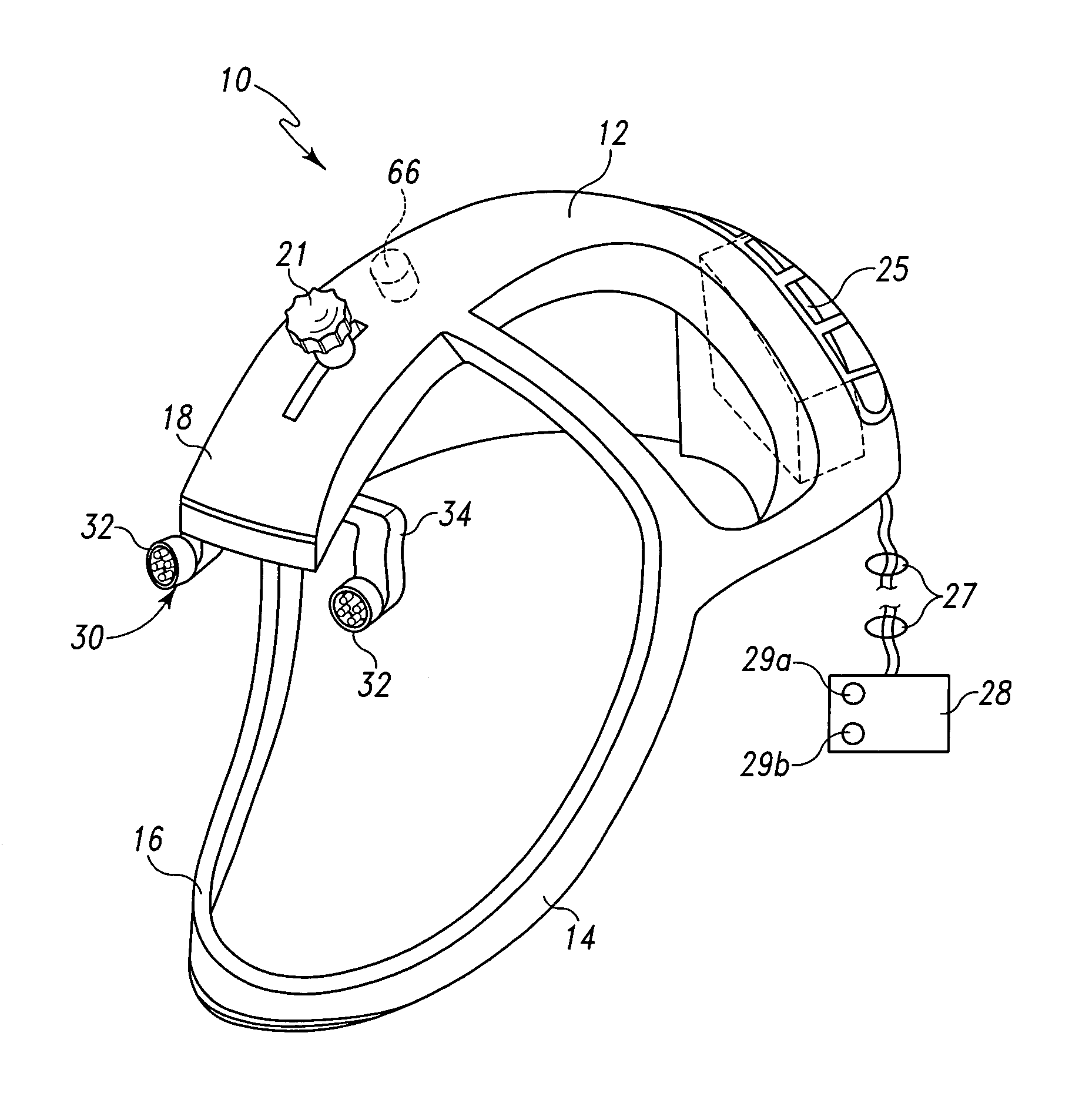
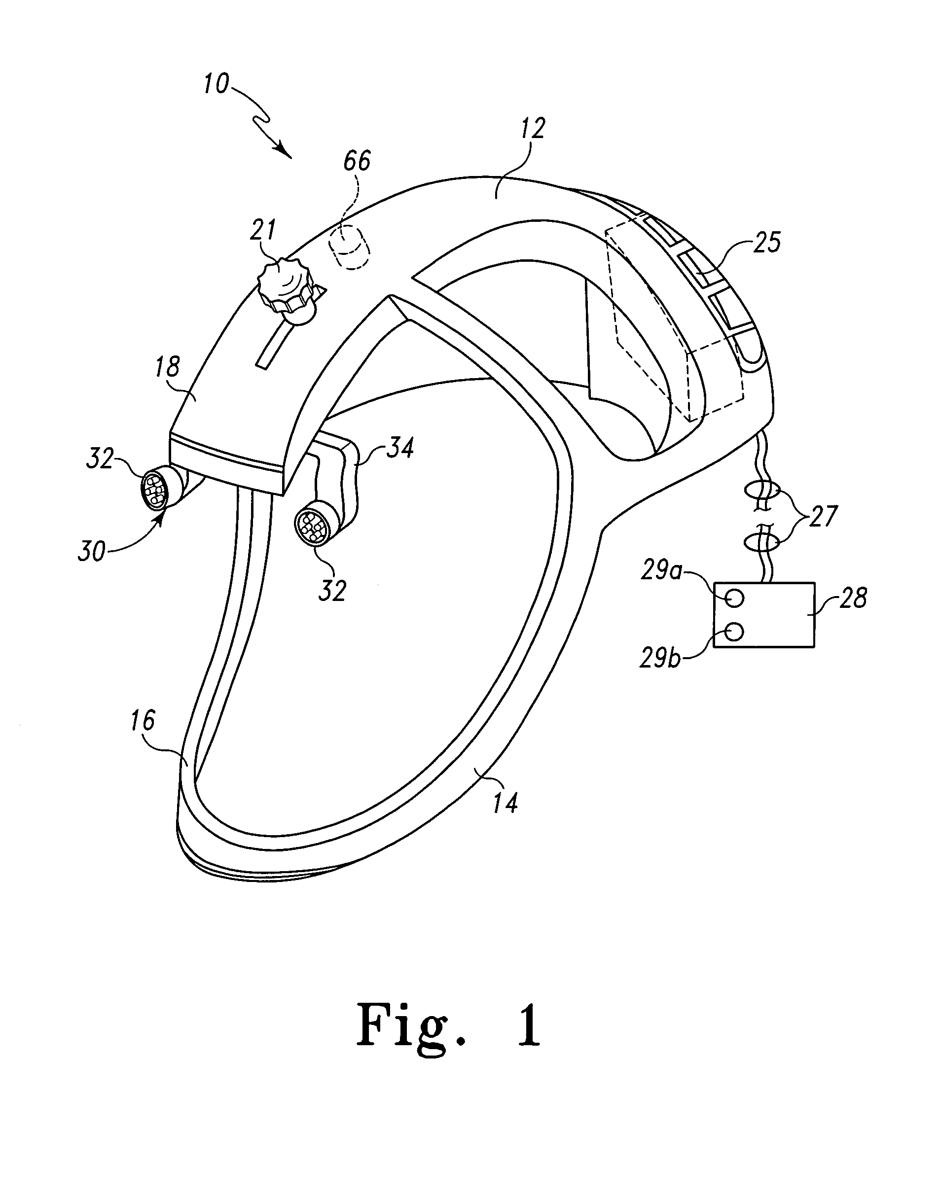
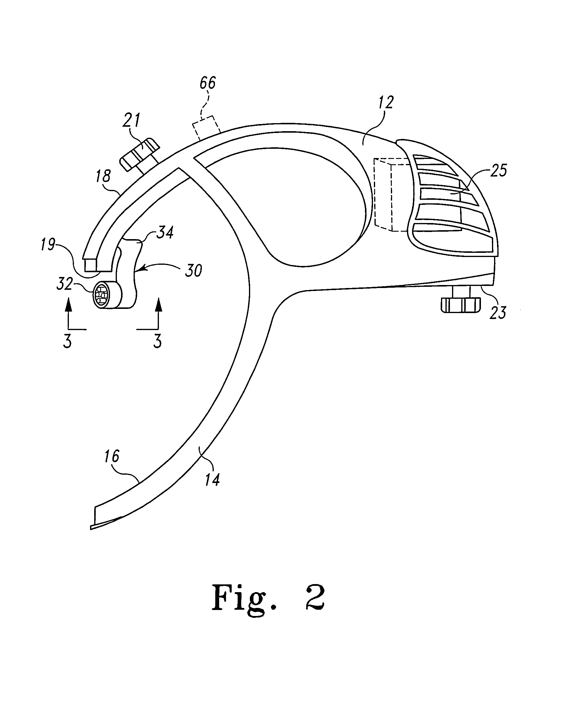
[0025]A shown in the detail view of FIG. 4, the present invention contemplates a light array 30 that is adapted to be mounted on a surgical helmet, such as the helmet 10 shown in FIGS. 1–2. The light array 30 includes a pair of light sources 32 situated on either side of the helmet 10, and particularly on the opposite sides of the ventilation duct 18, as shown in FIG. 1. The light sources 32 are carried by a mou...


PUM


Abstract

A surgical head gear apparatus or helmet includes a lighting system that utilizes circuit board mounted LED clusters supported on the surgical helmet. The LED clusters are part of a light array mounted to the forward portion of the helmet. In one embodiment, the light array is self-contained with its own power supply. In another embodiment, the light array is electrically connected to an external power supply and controller, such as en existing controller associated with the ventilation system of the helmet. In accordance with the invention, the only remote link for the LED clusters and circuit boards is to a control switch and / or power supply.

Description

BACKGROUND OF THE INVENTION[0001]The present invention is directed to a head gear apparatus or helmet for use with a garment worn by a medical caregiver during surgical procedures.[0002]In many surgical procedures, medical personnel wear garments that are intended to maintain a barrier between the personnel and the patient. This barrier helps maintain sterile conditions in the operating room by completely shrouding the medical personnel and their clothing. In addition, this barrier serves to protect the caregiver from exposure to blood and other body fluids. Various organizations, such as OSHA, promulgate recommendations regarding occupational exposure to fluid-borne pathogens during medical procedures. The surgical gown or shroud helps meet these recommendations.[0003]One such surgical gown, or personal protection system, is the PROVISION™ System, marketed by DePuy Orthopaedics Co., Inc. This system includes a helmet system that integrates with a barrier hood and gown. The hood and...

Claims


Application Information

Patent Timeline
Patent Type & Authority Patents(United States)
IPC IPC(8): F21V21/084A42C5/04
CPCA42B3/044F21L4/00F21L14/00F21V33/0008Y10S2/906F21W2131/205F21Y2101/02F21Y2115/10
Inventor CLUPPER, CHRISTIAN H.VENDRELY, TIMOTHY G.MCADAMS, DANNY E.HUNTSMAN, LEON
Owner DEPUY PROD INC
Why Eureka
Try Eureka