Twin-shaft vacuum pump and method of forming same

a vacuum pump and twin-shaft technology, applied in the direction of intermeshing engagement type engines, rotary piston engines, rotary or oscillating piston engines, etc., can solve the problems of high back flow loss, high manufacturing and testing costs, high cost, etc., and achieve cost-effective manufacturing. , the effect of reducing manufacturing costs

Active Publication Date: 2007-03-20
PFEIFFER VACUUM GMBH
View PDF17 Cites 1 Cited by
  • Summary
  • Abstract
  • Description
  • Claims
  • Application Information

AI Technical Summary

Benefits of technology

[0014]The method of forming a twin-shaft vacuum pump includes stamping and forming of discoid components having a predetermined shape; forming two rotors by mounting a predetermined plurality of the discoid components on two shafts, respectively, with a predetermined angular offset of the discoid components relative to each other; and securing the plurality of the discord components on respective shafts; and mounting the two rotors in a housing. By forming the rotors of twin-shaft vacuum pumps of separate discoid components, time-consuming and expensive machining processes are eliminated. The discoid components, the rotors are formed of, can be produced by a relatively cost-effective process, e.g., stamping.
[0046]the pump system can quickly be adapted, without manufacturing expenses, to new applications (a new assembly of the same pump),

Problems solved by technology

Both the manufacturing of the rotors and their testing is time-consuming and expensive.
However, the drawback of this consists in high back flow losses.
This results in high expenditure of time and high manufacturing and testing costs.
A further drawback of the conventional pumps consists in that the selection of materials is limited because of a need to take into consideration machining properties of the material.

Method used


Image

  • Twin-shaft vacuum pump and method of forming same
  • Twin-shaft vacuum pump and method of forming same
  • Twin-shaft vacuum pump and method of forming same

Examples


Embodiment Construction

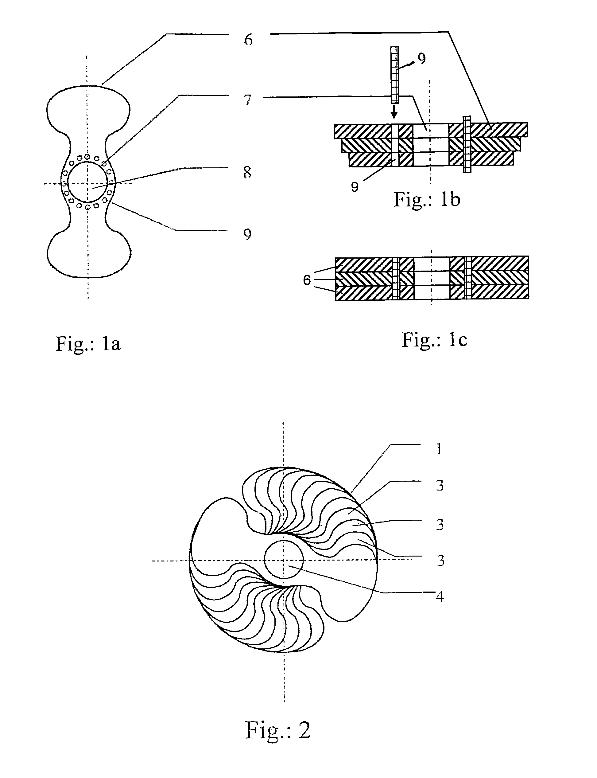
[0064]FIG. 2 shows a rotor 1 for twin-shaft vacuum pump according to the present invention and which is supported on a shaft 4. The rotor 1 is formed of a plurality of discoid components 3 offset relative to each other by the same angle.

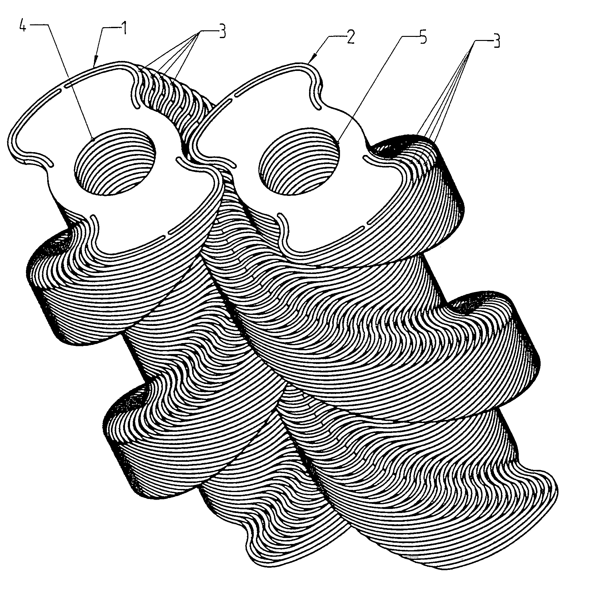
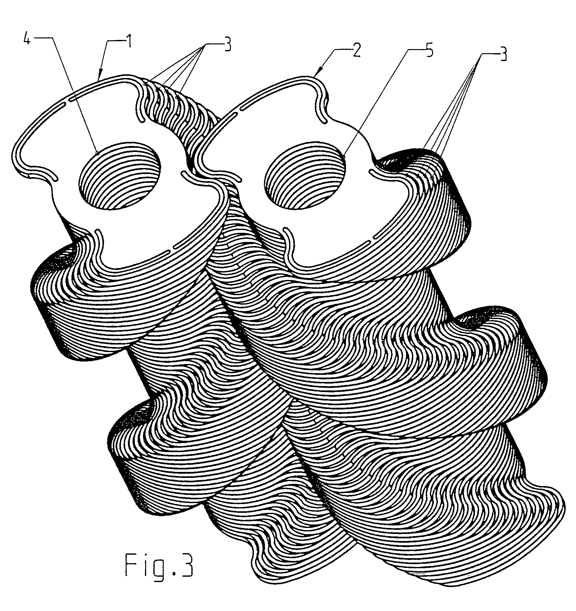
[0065]FIG. 3 shows two rotors 1 and 2 supported, respectively, on two shafts 4 and 5 of a twin-shaft vacuum pump. The rotor 2 is formed, as the rotor 1 shown in FIG. 2, of discoid components 3 likewise offset relative to each other at the same angle. With the components 3 of each rotor 1, 2 being offset relative to each other in a rotational direction of the rotors 1, 2, an outer profile of the rotors 1, 2 has a helical shape.

[0066]The component 3, of which the rotors 1 and 2 are formed, is shown in FIG. 1a. The component 3 is formed as a discoid member 6 having a receiving opening 7 for receiving a shaft 8 which extends therethrough. The receiving opening 7 is surrounded by a ring of holes 9. Upon forming a rotor of the discoid members 6, with the m...


PUM


Abstract

A twin-shaft vacuum pump includes two shafts and two rotors supported on respective shafts and cooperating with each other for producing a pumping effect, with each rotor being formed of a plurality of discoid components.

Description

BACKGROUND OF THE INVENTION[0001]1. Field of Invention[0002]The present invention relates to a twin-shaft vacuum pump and a method of producing or forming the same.[0003]2. Description of the Prior Art[0004]Multi-shaft vacuum pumps such as, e.g., screw pumps are widely used in dry pump systems, in particular, in chemical industry and in semiconductor technology. They consist essentially of a housing with two, crossing each other bores, and two helical rotors arranged in respective bores and rotatable in opposite directions. The two rotors are intermeshing roll over each other in a contactless manner. The cooperation of the two rotors produces a pumping action. The to-be-delivered gas is sucked through an inlet at one side of the rotors and is displaced axially toward the outlet. Due to the decreasing pitch of the screw thread from the inlet to the outlet, compression of the gas takes place.[0005]At a present state of the art, the rotors are formed as one-piece members. The rotors sh...

Claims


Application Information

Patent Timeline
Patent Type & Authority Patents(United States)
IPC IPC(8): F03C2/00F04C2/00F04C18/08F04C18/12F04C18/16F04C18/18F04C25/02F04C29/00
CPCF04C18/084F04C18/16F04C18/126
Inventor RIPPL, CHRISTOPHER-MARKWAGNER, JUERGEN
Owner PFEIFFER VACUUM GMBH
Why Eureka
Try Eureka