Twin-shaft vacuum pump and method of forming same

Active Publication Date: 2005-12-15
PFEIFFER VACUUM GMBH
View PDF5 Cites 1 Cited by
  • Summary
  • Abstract
  • Description
  • Claims
  • Application Information

AI Technical Summary

Benefits of technology

[0033] It is advantageous when a discoid component is formed as a one-piece member. This insures a most cost-effective manufacturing of discoid components.
[0

Problems solved by technology

Both the manufacturing of the rotors and their testing is time-consuming and expensive.
However, the drawback of this consists in high back flow losses.
This results in high expenditure of time and high manufa

Method used


Image

  • Twin-shaft vacuum pump and method of forming same
  • Twin-shaft vacuum pump and method of forming same
  • Twin-shaft vacuum pump and method of forming same

Examples


Embodiment Construction

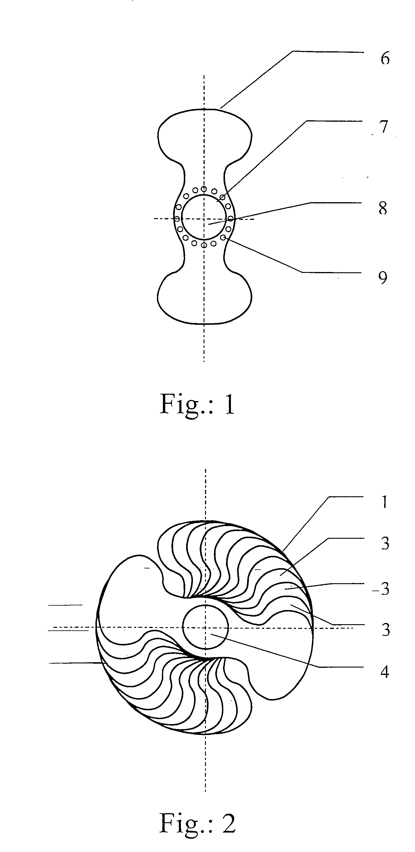
[0060]FIG. 2 shows a rotor 1 for twin-shaft vacuum pump according to the present invention and which is supported on a shaft 4. The rotor 1 is formed of a plurality of discoid components 3 offset relative to each other by the same angle.

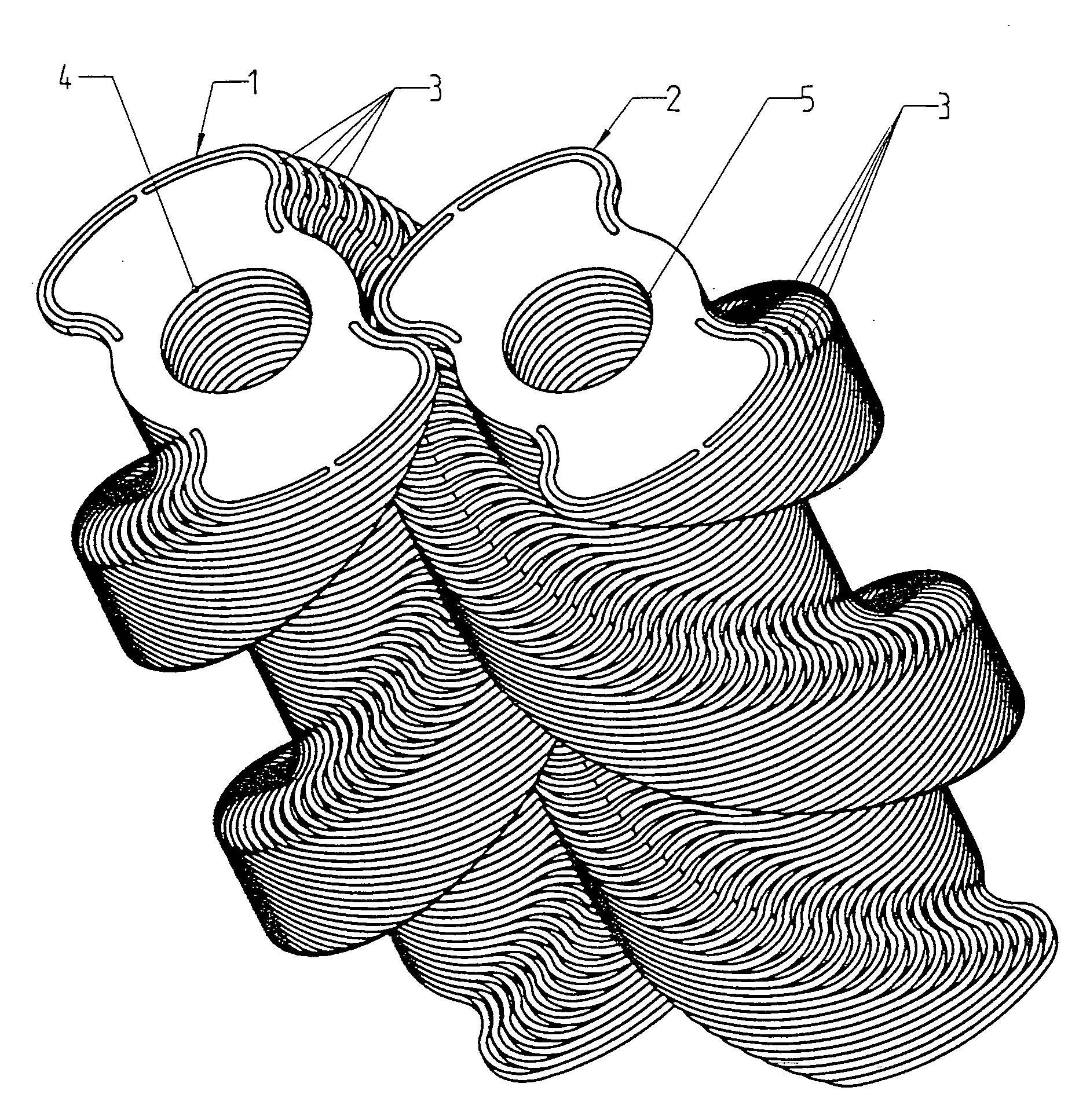
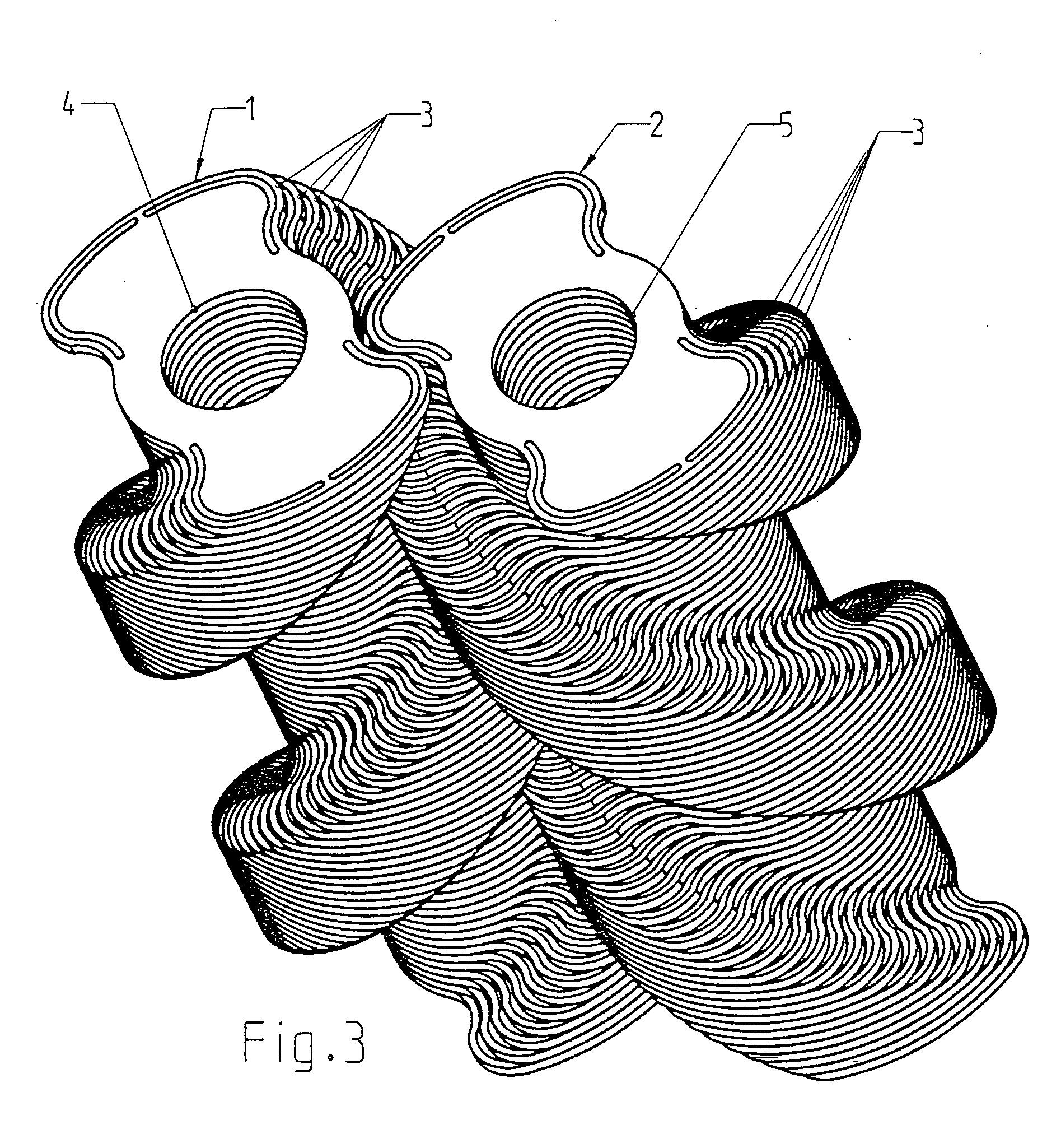
[0061]FIG. 3 shows two rotors 1 and 2 supported, respectively, on two shafts 4 and 5 of a twin-shaft vacuum pump. The rotor 2 is formed, as the rotor 1 shown in FIG. 2, of discoid components 3 likewise offset relative to each other at the same angle. With the components 3 of each rotor 1, 2 being offset relative to each other in a rotational direction of the rotors 1, 2, an outer profile of the rotors 1, 2 has a helical shape.

[0062] The component 3, of which the rotors 1 and 2 are formed, is shown in FIG. 1. The component 3 is formed as a discoid member 6 having a receiving opening 7 for receiving a shaft 8 which extends therethrough. The receiving opening 7 is surrounded by a ring of holes 9. Upon forming a rotor of the discoid members 6, with the...


PUM


Abstract

A twin-shaft vacuum pump includes two shafts and two rotors supported on respective shafts and cooperating with each other for producing a pumping effect, with each rotor being formed of a plurality of discoid components.

Description

BACKGROUND OF THE INVENTION [0001] 1. Field of Invention [0002] The present invention relates to a twin-shaft vacuum pump and a method of producing or forming the same. [0003] 2. Description of the Prior Art [0004] Multi-shaft vacuum pumps such as, e.g., screw pumps are widely used in dry pump systems, in particular, in chemical industry and in semiconductor technology. They consist essentially of a housing with two, crossing each other bores, and two helical rotors arranged in respective bores and rotatable in opposite directions. The two rotors are intermeshing roll over each other in a contactless manner. The cooperation of the two rotors produces a pumping action. The to-be-delivered gas is sucked through an inlet at one side of the rotors and is displaced axially toward the outlet. Due to the decreasing pitch of the screw thread from the inlet to the outlet, compression of the gas takes place. [0005] At a present state of the art, the rotors are formed as one-piece members. The...

Claims


Application Information

Patent Timeline
IPC IPC(8): F04C18/08F04C18/12F04C18/16F04C18/18F04C25/02F04C29/00
CPCF04C18/084F04C18/16F04C18/126
Inventor RIPPL, CHRISTOPHER-MARKWAGNER, JUERGEN
Owner PFEIFFER VACUUM GMBH
Why Eureka
Try Eureka