System and method for biaxial semi-prefabricated lightweight concrete slab

a lightweight, flat-plate concrete technology, applied in the direction of structural elements, building components, construction materials, etc., can solve the problems of additional means, time-consuming and expensive horizontal scaffolding and temporary vertical supports, and labor for both erection and removal of supports, and achieve the effect of reducing the cost of labor and time-consuming

Active Publication Date: 2018-01-30
BREUNING KIM ILLNER
View PDF39 Cites 0 Cited by
  • Summary
  • Abstract
  • Description
  • Claims
  • Application Information

AI Technical Summary

Benefits of technology

[0041]The object of this development is to create a lightweight biaxial flat slab with span in any direction with at least 30× slab thickness and without temporary support. This object can be obtained through the optimal geometric balance between maximum material strength and minimum material mass (weight).
[0042]Compared to prior art, the present invention solves the time consuming and expensive process with temporary supports for semi-precast concrete slabs. The invention comprises a practical and cost efficient semi-precast building system by which voided homogeneous biaxial flat concrete slabs can be realized without the use of formwork or temporary supports—a configuration, which can be positioned directly on the buildings columns and / or walls and afterwards be fully concreted. In addition, the final slab has increased bearing capacity and improved regulation of deflection.

Problems solved by technology

The essential weakness is the horizontal scaffolding and temporary vertical supports, which are expensive and time consuming.
The weakness of fully pre-casted final elements are, that they per definition are one-way spanning elements and can only be used to achieve slabs spanning in one single direction, in contradiction to slabs concreted entirely or partly on the building site, which may be reinforced to carry in two directions.
Fully precast elements are individual parts, and may have also problems with vibrations, sound and general leakage, why additional means normally are necessary.
Furthermore, the process is time consuming and demands labour for both erection and removing the supports.
This bottom can be applied with a weak pre-stressing, but the effect is limited, and this can only increase span between supports marginally, due to the limited height of the concrete bottom, which cannot be increased due to demands of minimising load and optimising space for voids.
The essential problem is how to give a semi-precast element sufficient strength and stiffness to carry over large span—or same span as final slab—until final concreting has cured and working load can be added.
Placing the steel beam upon the plate opens for continuous steel reinforcing in the slab but the couplings cannot secure adequate transfer of the necessary forces between steel profile and concrete plate and besides, the effect of the steel beam itself will never be sufficient.
The remaining concrete cover is too thin to be stable and the contact surface between steel and concrete is too poor to transfer necessary shear forces.
Increasing plate thickness is unthinkable and unrealistic as this will remove the basic idea of the slab type.
Steel profiles closer than 0.6 m cannot longer perform a concrete slab, but is a one-way system of parallel steel beams that cannot in practice be integrated to compose a lightweight biaxial homogenous slab.
All these applications incorporating steel beam profiles are highly impracticable and expensive in material consumption, as only a part of the steel has a function.
However, the most important issue—if foot of steel profile is encapsulated in a thin concrete plate with 2 cm under and 2 cm above the steel foot—is that forces (in particular post-tension) cannot be secured transferred between the vulnerable thin concrete layers and the steel, because the concrete is not strong enough and if it was, it would require additional unpractical and expensive means like complicated anchors to secure the transfer.
Disadvantages are that it is a time consuming system made onsite; that the traditional beams can only span a relative short distance.
Due to this, the connected slab elements will compose a regular one-way structure without possibility for any two-way effect because continuity can only be established one way, due to the obstructing ridges at the sides.
Further, an essential problem with this invention is the use of ridge beams.
The fabrication and concreting of a semi-precast element incorporating such ridge beams results in problematic and expensive formwork as well as process, for which reason new system / methods are needed.
Furthermore, such a fabrication method excludes the possibility to have anything incorporated in the concrete extruding from the concrete in the same direction as the ridges compared to the panel, as the semi-precast elements with ridges necessarily must be made upside-down on the formwork.
This results in an expensive element with limited function and no flexibility.
However, the effect is very limited due to the thin concrete bottom and do not comply with full dead load over realistic span.
However, the use of pre-tensioning is ineffective, as the ability to transfer forces between beams and thin bottom plate is very limited.
This consequently limits the tension with can be applied to the beams, and as a result limits the carrying effect—and leaves the carrying effect to the beams alone.
Further, the effective height is limited to the effective height within the pre-tensioned beam itself, which furthers reduces the effect.
To date, there exist no solutions with regards to voided homogeneous biaxial concrete flat slabs to be erected without the use of temporary supports.

Method used


Image

  • System and method for biaxial semi-prefabricated lightweight concrete slab
  • System and method for biaxial semi-prefabricated lightweight concrete slab
  • System and method for biaxial semi-prefabricated lightweight concrete slab

Examples


Embodiment Construction

[0064]The invention comprises a practical and cost efficient semi-precast element system with which lightweight homogeneous biaxial concrete slabs can be realized without the use of formwork or temporary supports—a configuration, which can be positioned directly on a buildings vertical supports as columns or walls, and afterwards be connected by final concreting. In addition, the final slab has increased bearing capacity and improved control of deflection and cracking.

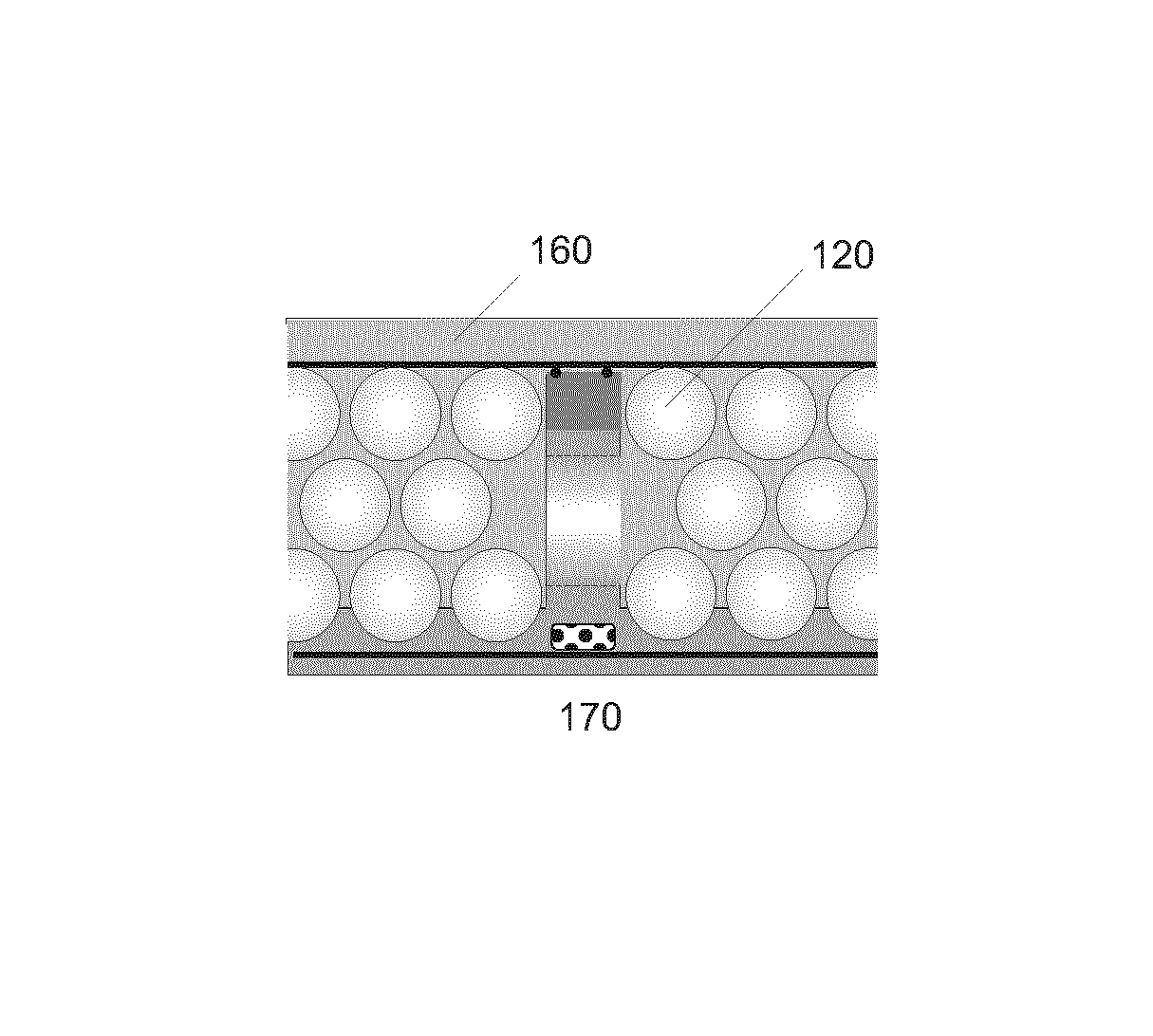
[0065]The key elements in the present invention are lightweight biaxial concrete slabs comprising unique composite semi-prefabricated stringers and semi-precast concrete elements in which the semi-precast stringers are integrated, and where post-tension tendons in the stringer are placed in an optimal way for maximum effect of post-tensioning of the semi-precast system, while still maintaining a simple and practical solution.

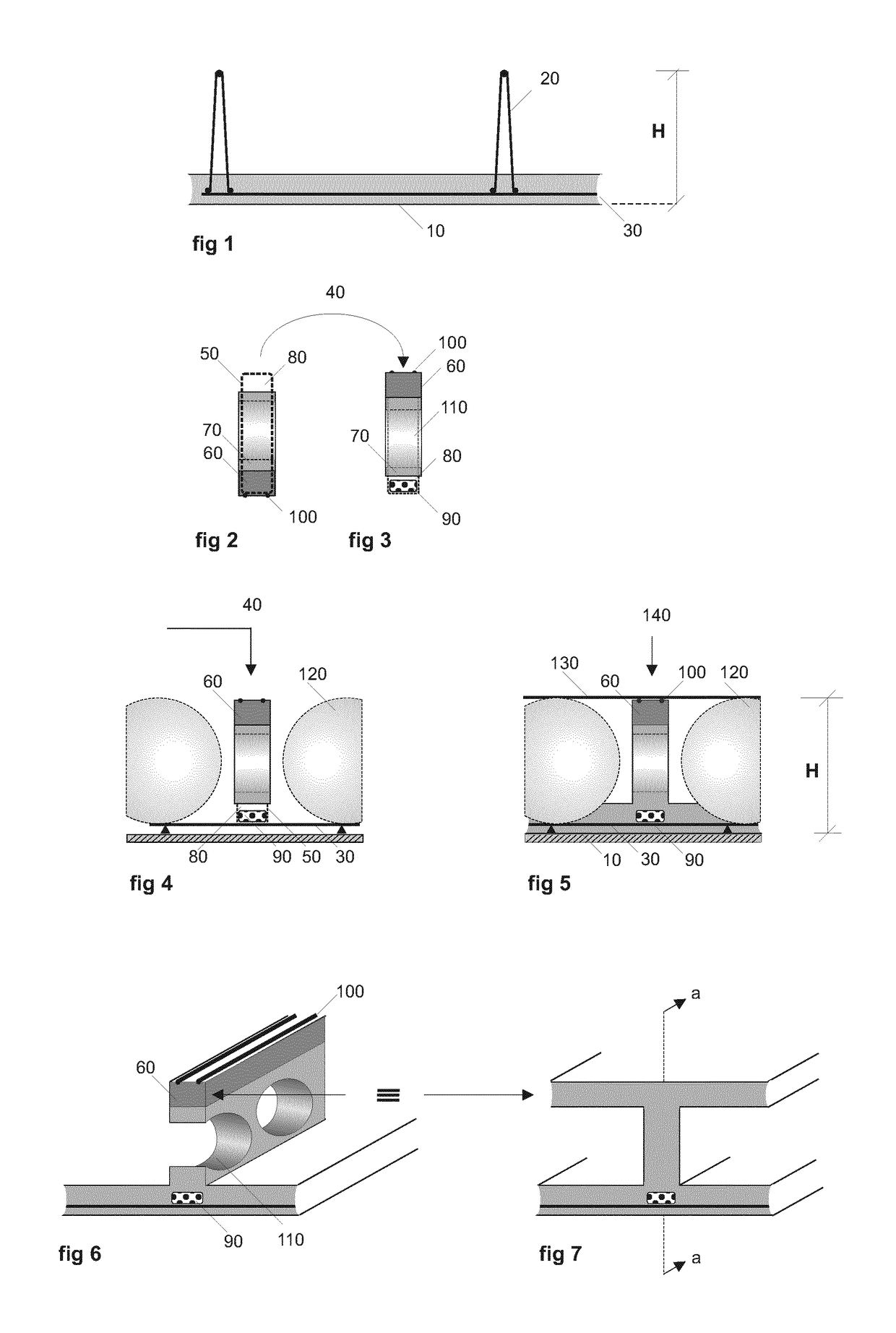
[0066]FIG. 1 illustrates a cross section cut in a traditional semi-precast element, where a thi...


PUM

PropertyMeasurementUnit
thicknessaaaaaaaaaa
strengthaaaaaaaaaa
speedaaaaaaaaaa

Abstract

The present invention solves the existing problem of obtaining a self-carrying biaxial homogeneous lightweight concrete slab. The present invention consists of a system and method comprising semi prefabricated elements and special stringer structures, designed in such a way, that the finished flat slab structure appears homogeneous and can be achieved without temporary supports during the execution. The present invention solves the problem in a simple and economical manner, increasing building speed, and providing an enhanced range of applicability.

Description

BACKGROUND OF THE INVENTION[0001]Field of the Invention[0002]The invention relates to the design, production and implementation of a lightweight biaxial flat plate concrete slab system, comprising semi-prefabricated elements, designed and produced in such a way, that post-tensioning of part of the system, facilitates a finished slab structure that is homogeneous and can be achieved without temporary supports during the execution.[0003]Prior art lacks the ability to achieve homogeneous biaxial slabs without temporary supports, and the present invention solves these issues in a simple and economical manner. The enhanced range of applicability will lead to increased building speed, as well as environmental benefits through material reduction.[0004]Description of the Prior Art[0005]Concrete slabs can be regarded in three main groups based on the relevant criteria of function and execution: slabs fully concreted on site; fully precast elements or semi-precast elements. Each of these main...

Claims


Application Information

Patent Timeline
Patent Type & Authority Patents(United States)
IPC IPC(8): E04B1/48B28B1/00E04B5/38E04B5/36E04C5/01E04B5/32E04C5/08
CPCE04B5/36B28B1/004E04B5/328E04C5/01E04C5/08E04B5/38E04B2103/02E04B2005/322E04B5/32
Inventor BREUNING, KIM ILLNER
Owner BREUNING KIM ILLNER
Why Eureka
Try Eureka