

Motion controlling hinge for orthopedic brace
a technology of motion control and hinges, applied in the field of orthopaedic bracing, can solve the problems of degenerative changes in the joint, injury to other structures, and people often having difficulty avoiding small flexion angles during normal activities
- Summary
- Abstract
- Description
- Claims
- Application Information
AI Technical Summary
Benefits of technology
Problems solved by technology
Method used
Image

Examples
Embodiment Construction
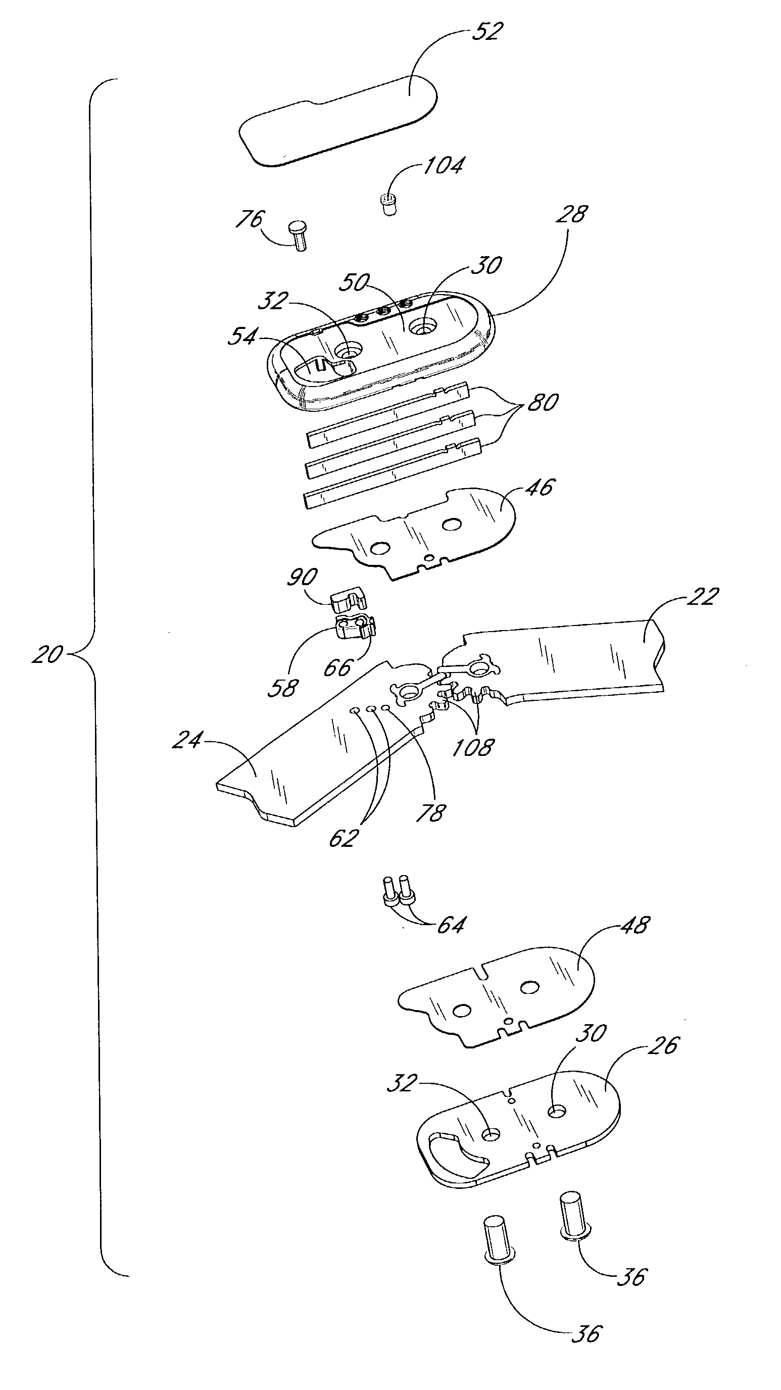
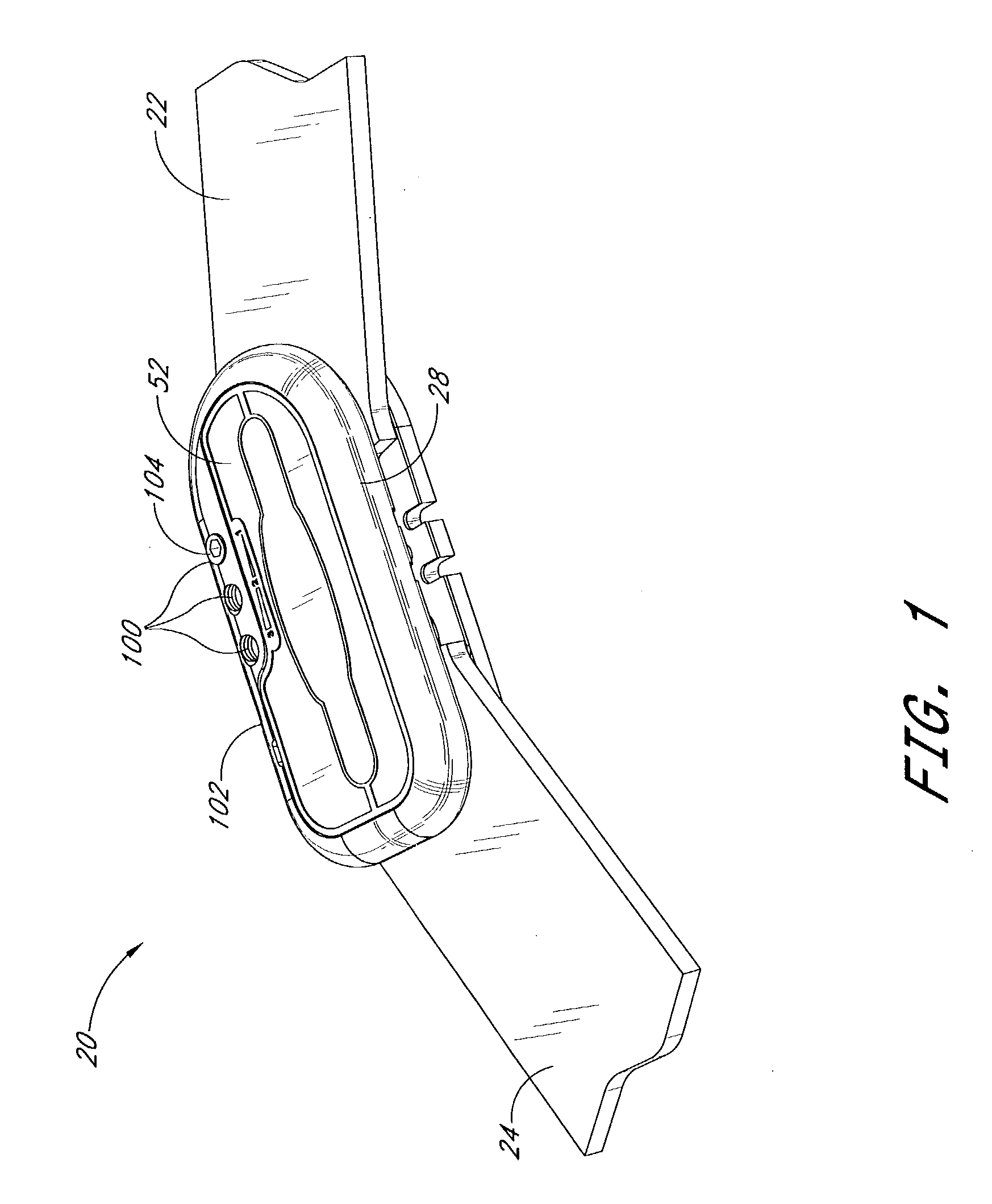
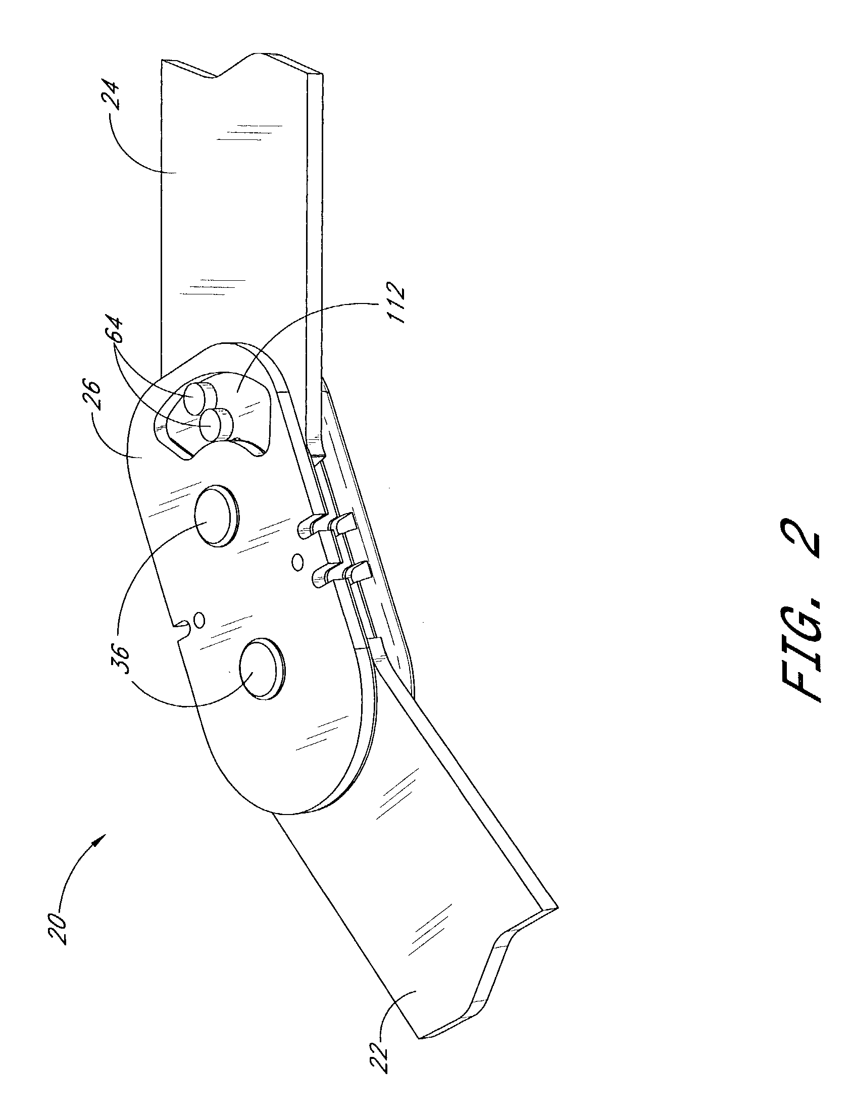
,” one will understand how the features of the preferred embodiments provide advantages, which include easy adjustability of a magnitude of a force that restrains hinge motion, and easy adjustability of an angle at which the hinge motion controlling force is applied.
[0014]A preferred embodiment of the hinge for orthopedic brace comprises a hinge plate, a spring member, and first and second arms pivotably secured to the hinge plate. An actuator is secured to the second arm. As the arms pivot in a first direction such that an angle between them increases, once the arms reach a desired extension angle, the spring member exerts a force on the actuator tending to bias the second arm in a second direction opposite the first direction.
[0015]Another preferred embodiment of the hinge for orthopedic brace comprises an orthopedic brace including a hinge. The hinge comprises a hinge plate, a spring member and first and second arms pivotably secured to the hinge plate. An actuator is secured to ...
PUM
 Abstract
Description
Claims
Application Information