Angle sensor having low waveform distortion

a sensor and waveform technology, applied in the field of angle sensors, to achieve the effect of reducing the deviation of magnetization and reducing the waveform distortion of output voltag

Inactive Publication Date: 2007-03-20
ALPS ALPINE CO LTD
View PDF9 Cites 10 Cited by
  • Summary
  • Abstract
  • Description
  • Claims
  • Application Information

AI Technical Summary

Benefits of technology

[0023]Accordingly, it is an object of the present invention to provide an angle sensor that exhibits a smaller waveform distortion of the output voltage than conventional angle sensors by the reduction of the AMR effect and the influence of the shape anisotropic magnetic field.

Problems solved by technology

However, in practice, the magnetization direction of the free magnetic layer is not identical to the direction of the external magnetic field.

Method used


Image

  • Angle sensor having low waveform distortion
  • Angle sensor having low waveform distortion
  • Angle sensor having low waveform distortion

Examples


Embodiment Construction

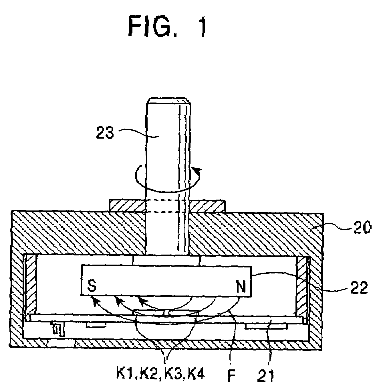
[0059]As shown in FIG. 1, a rotation angle sensor according to the present invention comprises a planar support (a fixed part) 21, which is made of a nonmagnetic material and is fixed on a case 20, and a rotor, which is disposed over the support 21 and has a discoidal magnet 22. The magnet 22, which faces the fixed part 21 and is made of, for example, ferrite, is polarized radially. The magnet 22 has a thickness of several millimeters and a radius of several centimeters.

[0060]A rotary shaft 23 made of a nonmagnetic material is fixed to the rotor, protrudes from the case 20, and is rotatably supported on the case 20.

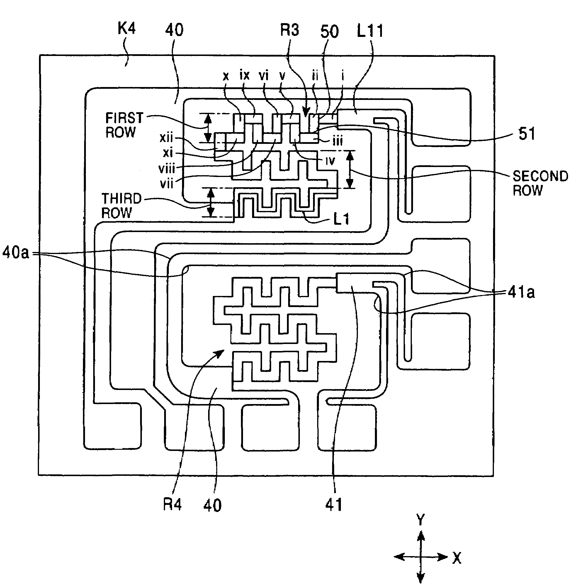
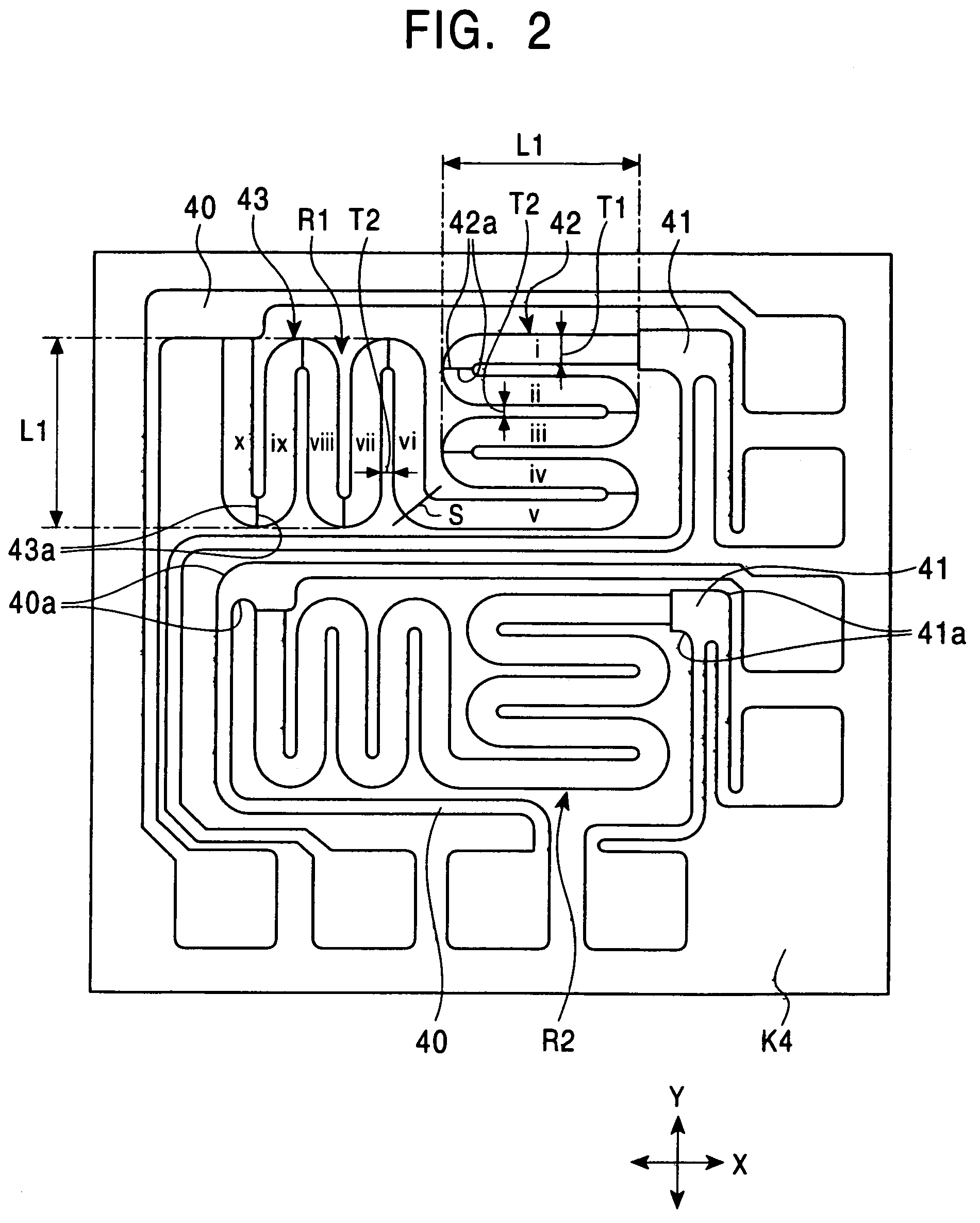
[0061]Substrates K1, K2, K3, and K4, each of which includes two magnetoresistive elements R1 and R2, as shown in FIG. 4, may be disposed on the support 21 and faces to the magnet 22.

[0062]The magnetoresistive elements R1 and R2 may be laminates, as shown in FIG. 6. The laminate may include an antiferromagnetic layer 30 made of PtMn alloy, a pinned magnetic layer 31 made o...


PUM


Abstract

A magnetoresistive element includes a meandering X-axis array that is constituted by X-axis segments alternately connected, and a meandering Y-axis array that is constituted by Y-axis segments alternately connected. When rotated 90°, the Y-axis array has the same layout as the X-axis array. Such a structure cancels the electrical resistance change due to the AMR effect, thus reducing the waveform distortion of output voltage.

Description

CROSS-REFERENCE TO RELATED APPLICATIONS[0001]This application is a divisional of U.S. patent application Ser. No. 10 / 879,674 filed on Jun. 28, 2004, by inventors Sudo et al. and entitled “ANGLE SENSOR HAVING LOW WAVEFORM DISTORTION,” which is incorporated herein by reference for all purposes.BACKGROUND OF THE INVENTION[0002]1. Field of the Invention[0003]The present invention relates to an angle sensor including a magnetoresistive element, such as a GMR element, and particularly to an angle sensor that can reduce the waveform distortion of output voltage.[0004]2. Description of the Related Art[0005]Angle sensors including magnetoresistive elements are already known (see, for example, Japanese Unexamined Patent Application Publication No. 2002-303536).[0006]The magnetoresistive element is a laminate that essentially consists of an antiferromagnetic layer, a pinned magnetic layer, a nonmagnetic material layer, and a free magnetic layer. The pinned magnetic layer is unidirectionally ma...

Claims


Application Information

Patent Timeline
Patent Type & Authority Patents(United States)
IPC IPC(8): G01B7/30G01R33/09H01L43/08G01D5/18G01B7/14G01D5/14G01D5/16
CPCG01D5/145
Inventor SUDO, YOSHIHIROTOKUNAGA, ICHIROSHIMIZU, YOSHIKAZUHASEGAWA, NAOYAKOIKE, FUMIHITO
Owner ALPS ALPINE CO LTD
Why Eureka
Try Eureka