
Pulse switch control device and control method thereof

A pulse switch and control device technology, applied in the direction of output power conversion devices, electrical components, etc., can solve the problems of shortening the service life of the power supply, reducing the reliability of the power supply, and failing to provide a discharge circuit

Inactive Publication Date: 2011-04-06
CHINA UNIV OF PETROLEUM (BEIJING)
View PDF3 Cites 10 Cited by
  • Summary
  • Abstract
  • Description
  • Claims
  • Application Information

AI Technical Summary

Problems solved by technology

However, because the existing paired control method of the H-bridge transmitting pulse circuit cannot provide a suitable discharge circuit, it will also affect the frequency, duty cycle and pulse width of the electric dehydration and desalination power supply pulse, and cannot provide a high-frequency pulse electric field
[0008] (3) The previous analysis shows that due to the need to discharge to the power supply, it will have an impact on the electronic devices in the power supply during the discharge process, which not only reduces the reliability of the power supply, but also shortens the service life of the power supply
[0009] (4) At the same time, the impact on the DC power supply when discharging to the power supply will be coupled to other windings of the switching power supply transformer, causing the voltage instability of the multi-channel transformer and its windings

Method used


Image

  • Pulse switch control device and control method thereof
  • Pulse switch control device and control method thereof
  • Pulse switch control device and control method thereof

Examples


no. 1 example

[0053] Figure 4a ~ Figure 4c It is the working principle diagram of the first embodiment of the pulse switch control device of the present invention, the control module of the present invention is controlled by the control terminal u 1 , u 2 , u 3 and u 4 hint.

[0054] When a forward pulse is applied to the load, the first control terminal u in the control unit 1 and the fourth control terminal u 4 respectively to the first switching unit S 1 The switching tube V T1 and the fourth switching unit S 4 The switching tube V T4 Send a conduction control signal to control the first switch unit S 1 and the fourth switching unit S 4 conduction, the second control terminal u in the control unit 2 and the third control terminal u 3 respectively to the second switching unit S 2 The switching tube V T2 and the third switching unit S 3 The switching tube V T3 Send a shutdown control signal to control the second switch unit S 2 and the third switching unit S 3 Turn off t...

no. 2 example

[0057] Figure 5a ~ Figure 5c It is the working principle diagram of the second embodiment of the pulse switch control device of the present invention, the control module of the present invention is controlled by the control terminal u 1 , u 2 , u 3 and u 4 hint. On the basis of the above-mentioned technical solution of the first embodiment, the present embodiment is provided with a discharge load R on the discharge circuit, and the discharge current is reduced through the discharge load R to effectively protect the switch tube. Specifically, the discharge load R in this embodiment is set between the first node A and the second switch unit S 2 between. In practical applications, the discharge load R can be set in conjunction with the second switch unit S 2 on the line connected in series, that is, it can be set on the second switch unit S 2 either side of the .

[0058] When a positive pulse is applied to the load, the working principle of this embodiment is the same a...

no. 3 example

[0061] Figure 6a and Figure 6b It is the working principle diagram of the third embodiment of the pulse switch control device of the present invention, the control module of the present invention is controlled by the control terminal u 1 , u 2 , u 3 and u 4 hint.

[0062] When a positive pulse is applied to the load, the working principle of this embodiment is the same as that of the first embodiment, the positive current loop LP 1 For: the positive pole of the DC power supply → the first switch unit S 1 The switching tube V T1 → first node A → load R L → second node B → fourth switch unit S 4 The switching tube V T4 → DC power supply negative pole, to the load R L Applying a forward pulse, such as Figure 4a shown.

[0063] When the positive pulse is applied to the load and stops, the first control terminal u in the control unit 1 and the third control terminal u 3 respectively to the first switching unit S 1 The switching tube V T1 and the third switching u...


PUM


Abstract

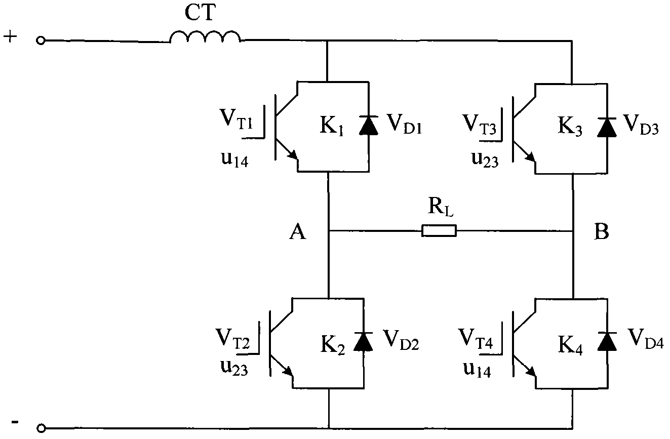
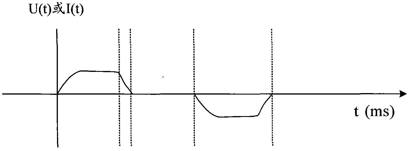
The invention relates to a pulse switch control device and a control method thereof. The pulse switch control device comprises an H-shaped bridge type transmitted pulse module consisting of a first switch unit, a second switch unit, a third switch unit and a fourth switch unit, and a control module, wherein one diagonal switch group consists of the first switch unit and the fourth switch unit, and the other diagonal switch group consists of the second switch unit and the third switch unit; one opposite switch group consists of the first switch unit and the third switch unit, and the other opposite switch group consists of the second switch unit and the fourth switch unit; the control module is connected with each switch unit respectively; when pulse is transmitted, the control module is used for controlling the switch units in one diagonal switch group to be switched on, and controlling the switch units in the other diagonal switch group to be switched off to form a pulse loop; and when the pulse transmission is stopped, the control module controls the switch units in one opposite switch group to be switched on and controls the switch units in the other opposite switch group to be switched off to form a discharging loop. Due to the formation of the discharging loop, trailing of pulse currents or voltages can be effectively eliminated, and the waveform distortion of the pulse currents or voltages is effectively reduced.

Description

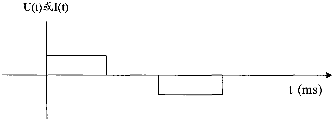
technical field [0001] The invention relates to a pulse emission technology, in particular to a pulse switch control device and a control method. Background technique [0002] Due to the advantages of simple control, fast switching speed, and bipolar output, the H-bridge transmitting pulse circuit is widely used in various devices as a switching converter for power conversion. For example, in the high-frequency high-voltage pulse power supply for electric dehydration and desalination of crude oil, the pulse switch control device is one of the more important components. The pulse switch control device uses the switching converter as the core to convert electric energy and realize electric power output. As another example, in the submarine oil and gas resource exploration launch device, the pulse switch control device is used to output the ideal current square wave. [0003] figure 1 It is a structural schematic diagram of an existing H-bridge transmitting pulse circuit. Su...

Claims


Application Information

Patent Timeline
Patent Type & Authority Applications(China)
IPC IPC(8): H02M1/08
Inventor 梁志珊邱银锋刘丽萱宋安阳魏学良
Owner CHINA UNIV OF PETROLEUM (BEIJING)
Learn More