In-ear monitor with hybrid dual diaphragm and single armature design

a dual diaphragm, in-ear monitor technology, applied in the field of audio monitors, can solve the problems of diaphragm receivers, affecting the fidelity of the sound, and the use of moving coil speakers, so as to improve the fidelity and reduce the cost

Active Publication Date: 2007-03-20
LOGITECH INT
View PDF14 Cites 34 Cited by
  • Summary
  • Abstract
  • Description
  • Claims
  • Application Information

AI Technical Summary

Benefits of technology

[0009]The present invention provides an in-ear monitor for use with either a recorded or a live audio source. The disclosed in-ear monitor combines a pair of diaphragm drivers and a single armature driver within a single earpiece, thereby taking advantage of the capabilities of both types of drivers. Preferably, the diaphragms are used to reproduce the lower frequencies while the higher frequencies are accurately reproduced by the armature driver. Such a hybrid design offers improved fidelity across the desired frequency spectrum and does so at a reduced cost in comparison to multiple armature designs. In addition to the three drivers, the in-ear monitor of the invention includes means for splitting the incoming signal into separate inputs for each driver. Typically this function is performed by a passive crossover circuit although an active crossover circuit can also be used. In at least one embodiment, acoustic dampers are interposed between one or more driver outputs and the eartip.

Problems solved by technology

Due to the inherent cost of armature receivers, however, they are typically only found in hearing aids and high-end in-ear monitors.
Diaphragm receivers, due to the use of moving-coil speakers, suffer from several limitations.
First, because of the size of the diaphragm assembly, a typical earpiece is limited to a single diaphragm.
This limitation precludes achieving optimal frequency response (i.e., a flat or neutral response) through the inclusion of multiple diaphragms.
Second, diaphragm-based monitors have significant frequency roll off above 4 kHz.
As the desired upper limit for the frequency response of a high-fidelity monitor is at least 15 kHz, diaphragm-based monitors cannot achieve the desired upper frequency response while still providing accurate low frequency response.
A single armature is capable of accurately reproducing low-frequency audio or high-frequency audio, but incapable of providing high-fidelity performance across all frequencies.
Unfortunately, as armatures do not excel at low-frequency sound reproduction, even in-ear monitors using multiple armatures may not provide the desired frequency response across the entire audio spectrum.
Additionally, the costs associated with each armature typically prohibit the use of in-ear monitors utilizing multiple armature drivers for most applications.
Although a variety of in-ear monitors have been designed, these monitors do not provide optimal sound reproduction throughout the entire audio spectrum.
Additionally, those monitors that achieve even a high level of audio fidelity are prohibitively expensive.

Method used


Image

  • In-ear monitor with hybrid dual diaphragm and single armature design
  • In-ear monitor with hybrid dual diaphragm and single armature design
  • In-ear monitor with hybrid dual diaphragm and single armature design

Examples


Embodiment Construction

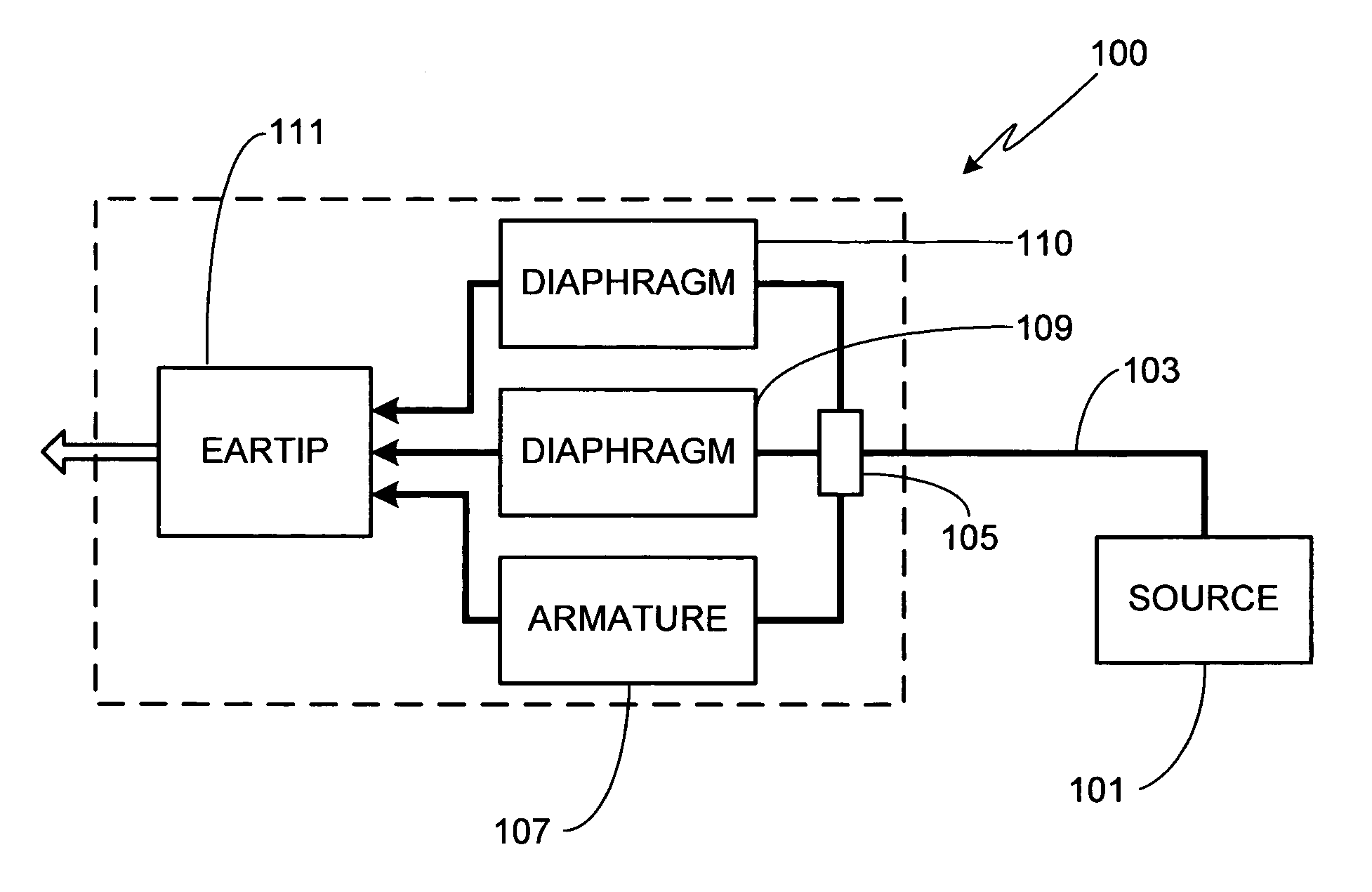
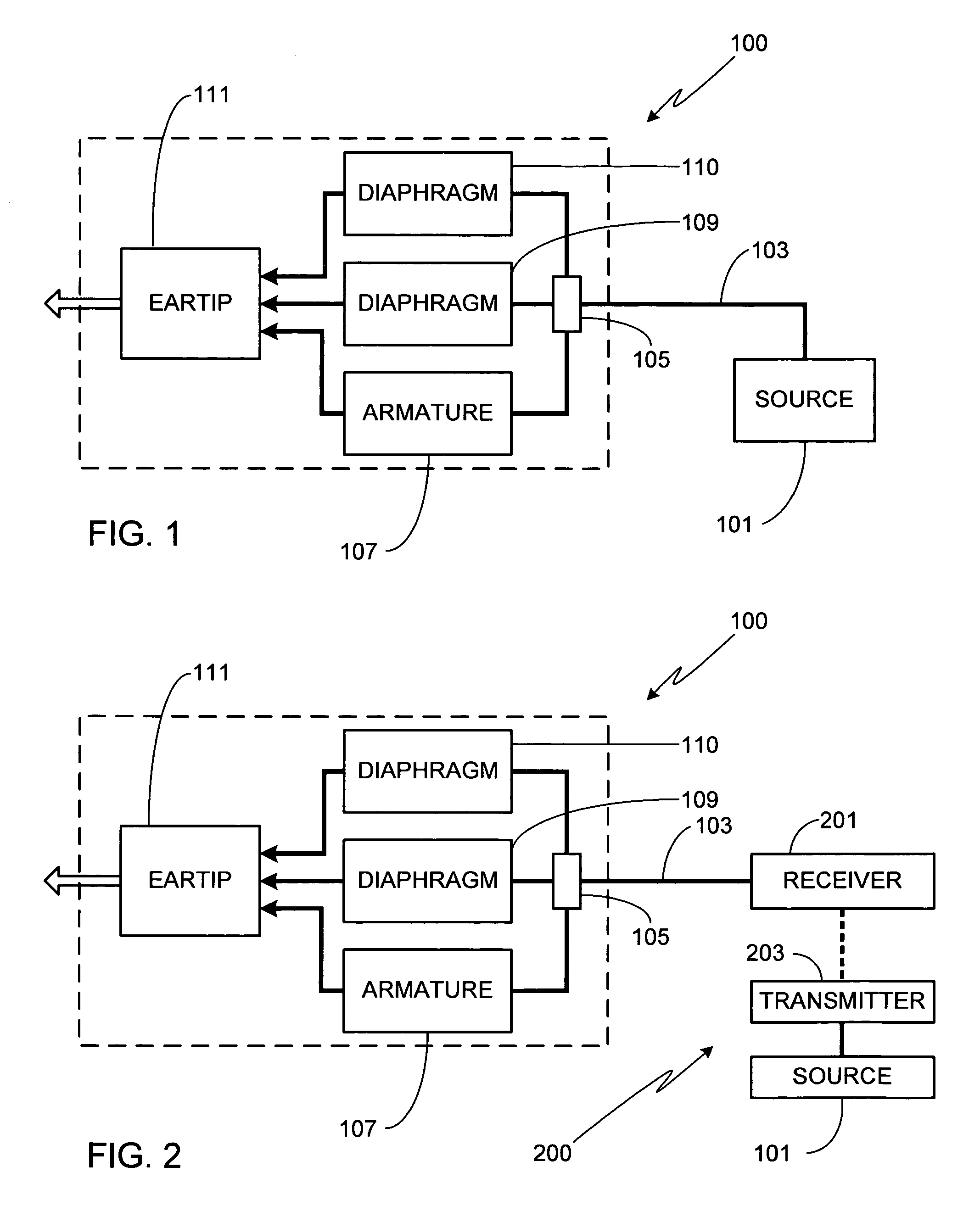
[0016]FIG. 1 is a block diagram of an in-ear monitor 100 in accordance with the invention. In this embodiment monitor 100 is coupled to source 101 via cable 103. Source 101 may be selected from any of a variety of sources such as an audio receiver, mixer, music player, headphone amplifier or other source type. The electrical signal from source 101 is feed through circuit 105 which provides input to armature driver 107 and a pair of diaphragm drivers 109 / 110, the electrical signal from source 101 representing the sound to be generated by in-ear monitor 100. The sounds produced by drivers 107, 109 and 110 are directed through an eartip 111 to the user.

[0017]FIG. 2 illustrates the use of in-ear monitor 100 with a wireless system. As shown, cable 103 is coupled to a receiver 201. Receiver 201 is wirelessly coupled to a transmitter 203 which is, in turn, coupled to source 101. If desired transmitter 203 and source 101 can be combined into a single device. It will be appreciated that in-e...


PUM


Abstract

An in-ear monitor for use with either a recorded or a live audio source is provided. The disclosed in-ear monitor combines a pair of diaphragm drivers and a single armature driver within a single earpiece, thereby taking advantage of the capabilities of both types of driver. Preferably, the diaphragm is used to reproduce the lower frequencies while the higher frequencies are accurately reproduced by the armature driver. Such a hybrid design offers improved fidelity across the desired frequency spectrum and does so at a reduced cost in comparison to multiple armature designs. In addition to the two drivers, the disclosed in-ear monitor includes means for splitting the incoming signal into separate inputs for each driver. Typically this function is performed by a passive crossover circuit although an active crossover circuit can also be used. In at least one embodiment, acoustic dampers are interposed between at least one driver output and the eartip.

Description

CROSS-REFERENCES TO RELATED APPLICATIONS[0001]This application is a continuation-in-part of U.S. patent application Ser. No. 11 / 034,144, filed Jan. 12, 2005, and claims the benefit of U.S. Provisional Patent Application Ser. Nos. 60 / 639,407, filed Dec. 22, 2004, and 60 / 639,173, filed Dec. 22, 2004, the disclosures of which are incorporated herein by reference for any and all purposes.FIELD OF THE INVENTION[0002]The present invention relates generally to audio monitors and, more particularly, to an in-ear monitor.BACKGROUND OF THE INVENTION[0003]In-ear monitors, also referred to as canal phones and stereo headphones, are commonly used to listen to both recorded and live music. A typical recorded music application would involve plugging the monitor into a music player such as a CD player, flash or hard drive based MP3 player, home stereo, or similar device using the monitor's headphone jack. Alternately, the monitor can be wirelessly coupled to the music player. In a typical live musi...

Claims


Application Information

Patent Timeline
Patent Type & Authority Patents(United States)
IPC IPC(8): H04R25/00
CPCH04R1/1016H04R11/02H04R9/063
Inventor HARVEY, JERRY J.
Owner LOGITECH INT
Why Eureka
Try Eureka