Sanitary nail clippers

a nail clipper and sanitary technology, applied in the field of fingernail and toenail clippers, can solve the problems of exposing the cutting edge of each jaw, no integral guard that would prevent the user from cutting the nail, and the structure of conventional nail clippers, so as to prevent intentional or accidental injury

Inactive Publication Date: 2007-03-27
WEISS EDWARD
View PDF11 Cites 2 Cited by
  • Summary
  • Abstract
  • Description
  • Claims
  • Application Information

AI Technical Summary

Benefits of technology

[0010]It is, therefore, an object of the present invention to provide effective fingernail and toenail clippers having a shielded, but visible, cutting edge for preventing intentional or accidental injury.
[0011]It is another object of the present invention to provide nail clippers having an integral vessel for collecting clipped nails, with removable cover to allow convenient discarding at will.

Problems solved by technology

There are at least three primary disadvantages to the structure of conventional nail clippers.
A first disadvantages is that the cutting edges on each jaw are exposed.
A second disadvantages is that there is no integral guard that would prevent the user from cutting the nail too far down.
Given the exposed cutting edges and lack of safety guard, conventional clippers may cause accidental injury if used by children or in an irresponsible manner.
A third notable disadvantage is that the conventional nail clippers spew out all nail clippings, leaving an unsanitary mess behind.
The Husain '137 patent attempts to provide a safety guard to prevent the user from cutting the nail down too far, but it does not address the problems of the exposed cutting edge or scattered nail clippings.
First, users may be reluctant to stick their fingernail in the slot to be clipped because the cutting edge is not visible.
Second, since the nail plate must pass through a slot the thickness of which is at least the sum of the thickness of both housing before reaching the cutting edge, the user may not be able to cut the nail as close to the hyponychium (point of attachment between the skin of the finger or toe and the distal end of the nail) as desired.
Lastly, while the Hansen '782 nail clippers provide an outlet for expelling the clipped nails, they do not provide a means to collect the clipped nails and expel them as desired (i.e. over a trash can).

Method used


Image

  • Sanitary nail clippers
  • Sanitary nail clippers
  • Sanitary nail clippers

Examples


Embodiment Construction

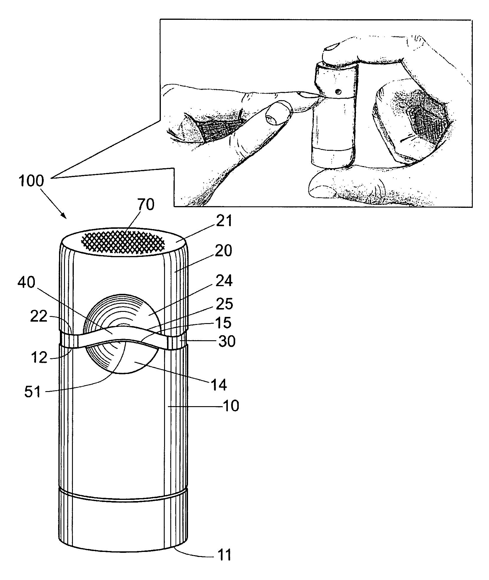
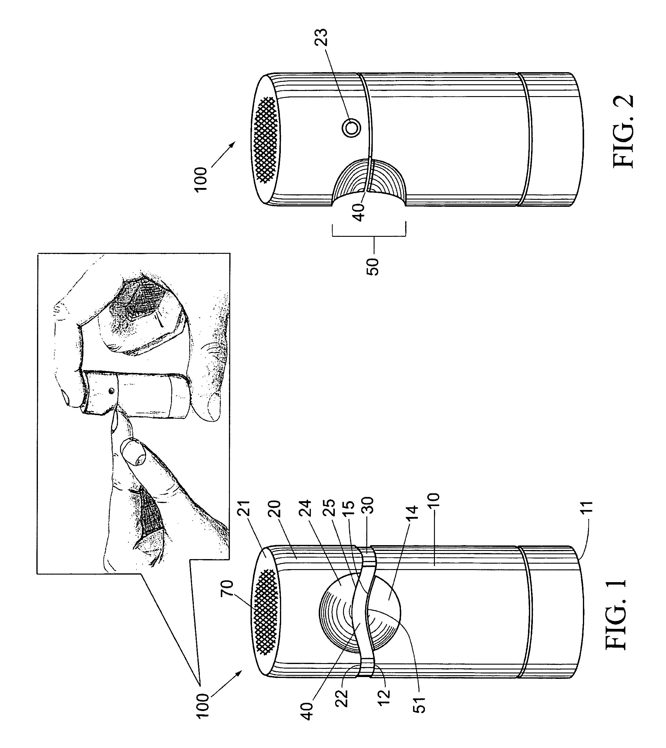
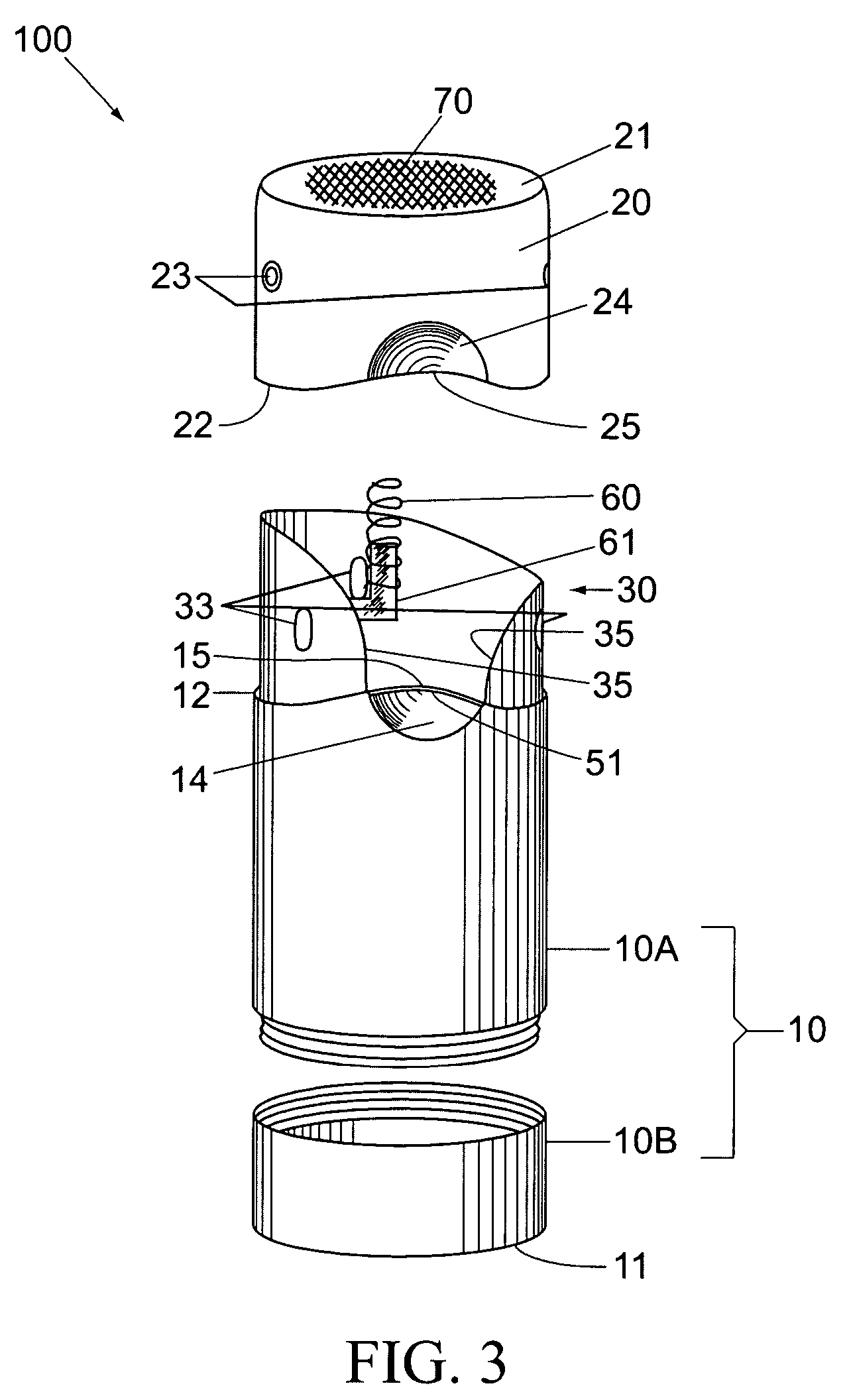
[0021]Referring to FIG. 1, the present invention is a sanitary nail clipper 100, generally comprising first and second hollow cylindrical housing sections 10, 20, each having substantially the same diameter and with opposing open ends 12, 22 having facing annular edges. The facing edges of the first and second housing sections 10, 20 are further defined by corresponding indentations that define concave lips 14, 24, the facing edges within the concavity being sharpened to form opposing cutting edges 15, 25. A tubular guide / connector 30 having an external diameter conforming to the interior of the first and second housing sections 10, 20 is fixedly anchored in the second section 10 and is slidably inserted into the first housing section 20. When the first and second housing sections 10, 20 are interconnected by the guide / connector 30 a nail cutting slot 40 is defined, flanked by the two corresponding cutting edges 15, 25.

[0022]As seen in FIG. 2, the contour of the concave lips 14, 24 ...


PUM


Abstract

Nail clippers having both shielded cutting blades to prevent intentional or accidental injury and an integral means for collecting clipped nails. The nail clippers include two hollow cylindrical housings each having both a closed and open end. The edges of the open ends of both housings each have a corresponding concave sharpened section, forming the cutting edges of a nail clipping slot. The housings are both slideably connected to and spring biased against each other. A nail inserted into the nail clipping slot is clipped by squeezing the housings together. Clipped nails are collected in the closed end of one of the housings. The closed end may be opened and / or removed to discard the clippings.

Description

CROSS-REFERENCE TO RELATED APPLICATION(S)[0001]The present application derives priority from U.S. Provisional Patent Application 60 / 589,605 filed: Jul. 21, 2004.BACKGROUND OF THE INVENTION[0002]1. Field of the Invention[0003]The present invention relates to fingernail and toenail clippers and, more particularly, to clippers for cutting the distal end of the nail plate wherein the cutting edge is shielded and the structure of the clippers further comprises an integral clipping collector.[0004]2. Description of the Prior Art[0005]Conventional finger and toenail clippers are almost invariably comprised of lever-actuated jaws having exposed sharpened edges. The lever is attached to a post that that is fixedly mounted at one end to the first jaw and slidably mounted at the other end to the second jaw. The jaws are held open by a natural spring bias. They are closed by manipulating the lever, which compresses the second jaw towards the first. The distal end of the nail plate is placed bet...

Claims


Application Information

Patent Timeline
Patent Type & Authority Patents(United States)
IPC IPC(8): A45D29/02
CPCA45D29/02
Inventor WEISS, EDWARD
Owner WEISS EDWARD
Why Eureka
Try Eureka