Engineered solution for controlled buoyancy perforating

a perforating gun and buoyancy technology, applied in the direction of fluid removal, drilling machines and methods, borehole/well accessories, etc., can solve the problems of low or no compressive force capacity of wirelines, inability to carry weight, and inability to achieve balanced pressure at first shot, so as to reduce the weight of perforating guns and reduce or eliminate frictional resistance to horizontal placement of perforating guns

Active Publication Date: 2007-03-27
SUKUP RICHARD A
View PDF10 Cites 37 Cited by
  • Summary
  • Abstract
  • Description
  • Claims
  • Application Information

AI Technical Summary

Benefits of technology

[0030]An important object of the present invention, therefore, is to greatly reduce the weight of a perforating gun. Another important object of the invention is a method to control the buoyancy of a downhole tool to within about ±0.5 to about ±0.25 # / ft. An important corollary to these objectives is a method for controlling the buoyancy of a perforating gun. A similar objective of the invention is to substantially reduce or eliminate frictional resistance to horizontal placement of perforating guns. Also an objective of the present invention is a procedure for floating a perforating gun into a substantially horizontal bore hole position. A further object of the invention is a means and procedure for perforating a long, horizontal and underbalanced wellbore with a single perforating gun positioned by a single round trip.
[0031]Other objects of the invention may include a procedure for reducing or eliminating the need for tractors and carriage wheels to position a long perforating gun of maximum diameter for the well circumstance. Another object of the invention is a substantial reduction in the density of a shaped charge carrier, shaped charge cases and of a perforating gun assembled from these components. Also an invention object is substantial weight reduction in individual shaped charge cases. A still further object of the present invention is a perforating gun assembly that may be substantially supported buoyantly by wellbore fluids to reduce frictional forces acting on the assembly. Another object of the invention is a method and apparatus for placing horizontal perforating guns of extended length while substantially supported by well fluid buoyancy forces. It is also an object of the present invention to substantially increase the effective length of perforating guns. A methodical approach to determining and adjusting the buoyancy of a perforating gun to compliment the perforation objectives is also an object of the invention.
[0034]Another essential perforating gun property is the tensile hoop strength of the carrier wall. When the shaped charge explosives ignite, a large pressure surge is exerted internally of the carrier wall. If this pressure surge expands the carrier wall excessively, removal of the spent gun from the wellbore may be prevented.

Problems solved by technology

The enormous cost of each well is well known to the industry.
Wirelines have little or no capacity to transmit compressive force but nevertheless support considerable weight in the tensile mode.
However, only the first shot may be under underbalanced pressure conditions.
At the same time, however, the addition of wheels to the gun structure reduces the useful gun diameter and increases the gun weight.
Most damaging, however, is the loss of useful gun diameter which has the consequence of reducing the maximum size of shaped charge unit that may be used in the gun and hence, the size and depth of perforation.
Although tractor technology provides means to increase the length of a horizontal perforating gun, such means remain insufficient to position a single, 6000 ft. perforating gun of unified length in a substantially horizontal wellbore.
Such completions are still burdened by the need for incremental perforation procedures and multiple “round trips” into the well.
Obviously, 4 or 5 round trips into and out of a 35,000 foot well is enormously expensive.
Petroleum bearing earth strata are not often of uniform porosity and / or permeability.
A flow conducive pressure differential of greater in situ pressure in the formation than in the wellbore is characterized as an underbalance.
Following the first gun shot, it is no longer possible to reduce the internal wellbore pressure significantly below the in situ formation pressure.
Accordingly, many of the flow reticent perforation channels may not be flushed of perforation debris and therefore fail to produce the fluid flow rate that may otherwise be expected.
Both long and short length horizontal completions may be plagued by a reduction of shaped charge penetration capacity.
However, prior art perforating guns generally rest against the floor of the horizontal wellbore when the shot is taken.
Traversal of the asymmetry gap consumes and diverts a significant portion of the jet energy thereby reducing the penetration capacity.

Method used


Image

  • Engineered solution for controlled buoyancy perforating
  • Engineered solution for controlled buoyancy perforating
  • Engineered solution for controlled buoyancy perforating

Examples


Embodiment Construction

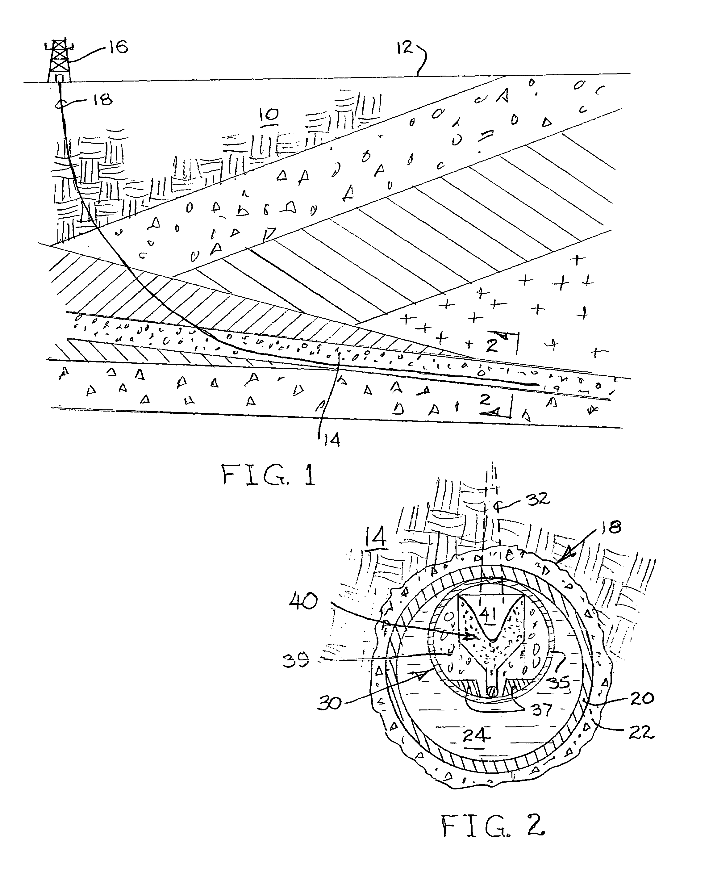
[0046]For environmental reference, FIG. 1 represents a cross-section of the earth 10. Below the earth surface 12, the earth firmament comprises a number of differentially structured layers or strata. A thin and mildly sloped strata 14 is of particular interest due to an abundant presence of petroleum.

[0047]From a drilling / production platform 16 on the earth surface 12, an extended wellbore 18 is drilled into and along the strata 14. In this case, the wellbore 18 is drilled to follow the bottom plane of the strata.

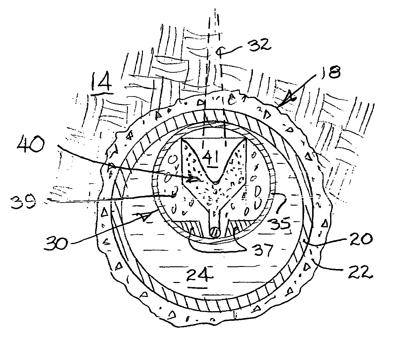
[0048]There are many well completion systems. Although the present invention is relevant to all completion systems in one form or another, the “cased hole” completion represented by FIG. 2 serves as a suitable platform for describing a presently preferred embodiment of the invention.

[0049]With respect to FIG. 2, traverse of the production strata 14 by the borehole 18 is lined by casing 20 set within a cement sheath 22. In the course of drilling and / or casing, the borehole 1...


PUM


Abstract

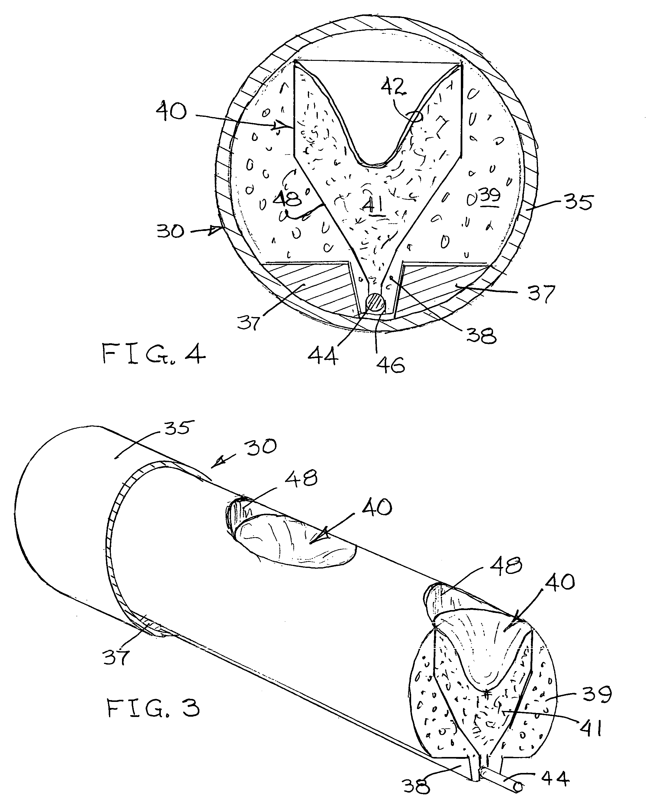
The weight of a shaped charge carrier is predetermined as a buoyancy control parameter for perforating guns. Each charge carrier comprises a co-axial assembly of inner and outer carrier units. Both carrier units may be fabricated from low density metals or composite materials comprising high strength fibers in a polymer matrix. The outer carrier wall thickness may be a weight control parameter. Shaped charge units having no independent casement are formed into sockets within a light-weight inner carrier unit. Alternatively, the shaped charge units may be formed within light-weight material cases and seated within sockets in the light-weight inner carrier unit. Materials and dimensions are selected to substantially achieve the desired carrier buoyancy in the specific well fluid whereby a perforating gun assembled from a plurality of the carriers may be substantially floated into a completion position and allowed to settle along the floor or ceiling of the wellbore as predetermined by the perforation direction.

Description

CROSS-REFERENCE TO RELATED APPLICATIONS[0001]Not Applicable.STATEMENT REGARDING FEDERALLY SPONSORED RESEARCH OR DEVELOPMENT[0002]Not Applicable.BACKGROUND OF THE INVENTION[0003]1. Field of the Invention[0004]This invention generally relates to downhole well tools and specifically to shaped charge perforating guns for subterranean wells.[0005]2. Description of Related Art[0006]Traditional petroleum drilling and production technology often includes procedures for perforating the wall of a production well bore to enhance a flow of formation fluid along perforation channels into the fluid bearing strata. Depending on the well completion equipment and method, it is necessary for such perforations to pierce the casing, production pipe or tube wall. In many cases, the casing or tube is secured to the formation structure by a cement sheath. In these cases, the cement sheath must be pierced by the perforation channel as well.[0007]There are three basic methods presently available to the indu...

Claims


Application Information

Patent Timeline
Patent Type & Authority Patents(United States)
IPC IPC(8): E21B43/116E21B43/119
CPCE21B43/119E21B43/116
Inventor SUKUP, RICHARD A.BELL, WILLIAM T.
Owner SUKUP RICHARD A
Why Eureka
Try Eureka