Stand for display

Inactive Publication Date: 2007-03-27
SAMSUNG ELECTRONICS CO LTD
View PDF240 Cites 97 Cited by
  • Summary
  • Abstract
  • Description
  • Claims
  • Application Information

AI Technical Summary

Benefits of technology

[0007]Accordingly, it is an aspect of the present invention to provide a stand for a display that is capable of supporting a display of substantial weig

Problems solved by technology

However, this type of stand cannot support heavy, large-sized displays.
But, this type of stand requires separate devices such as a plu

Method used


Image

  • Stand for display
  • Stand for display
  • Stand for display

Examples


Example

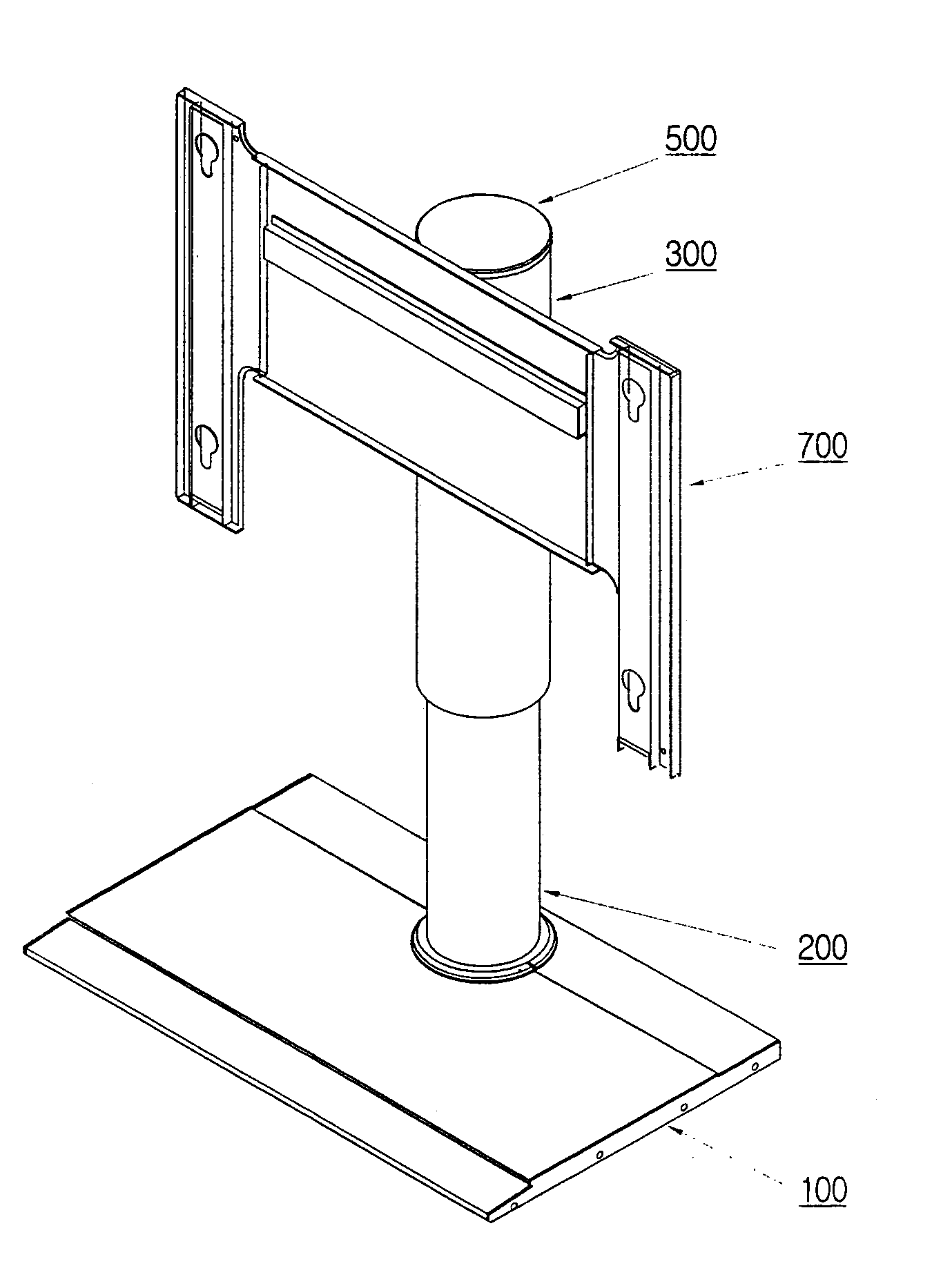
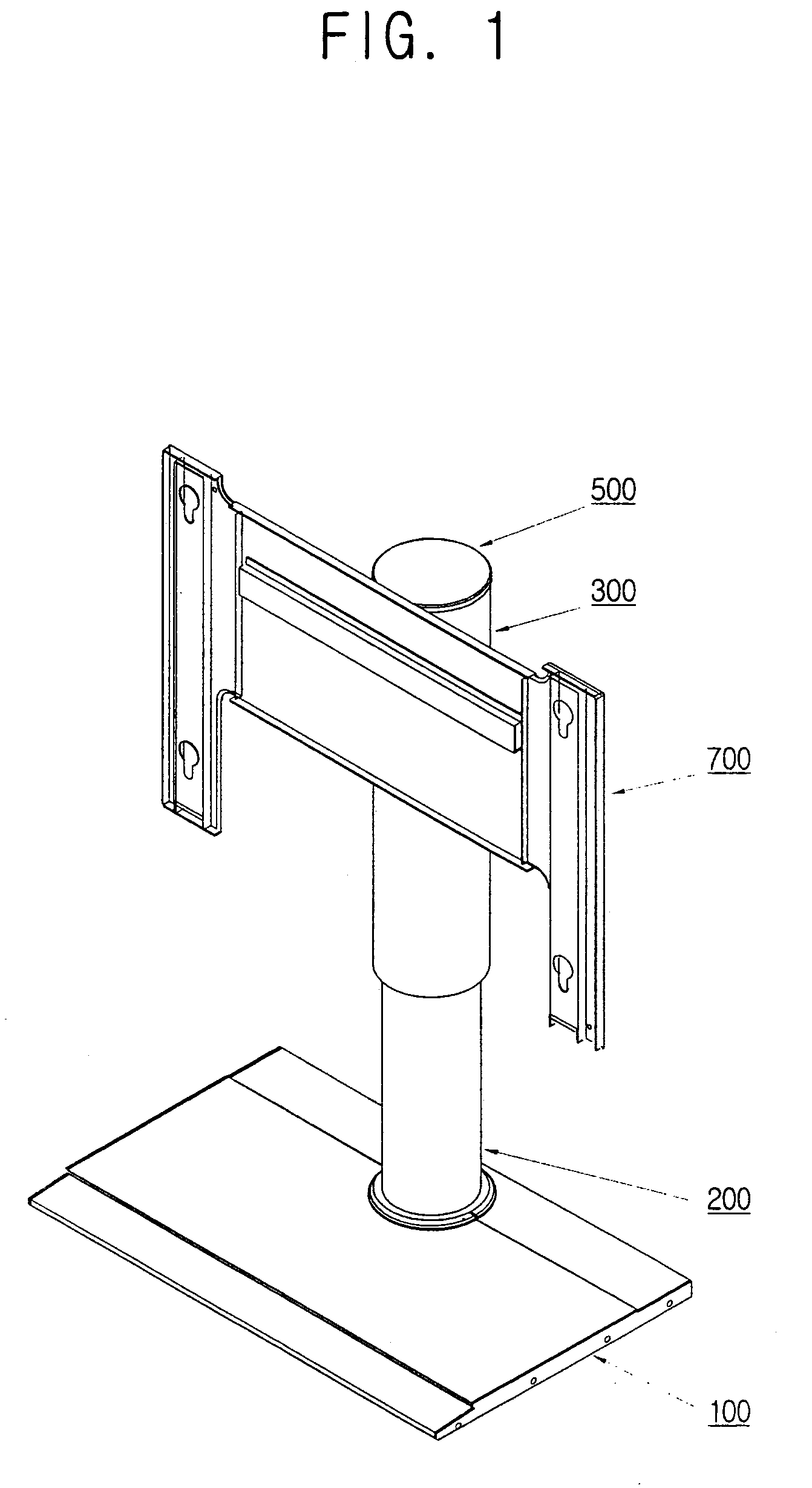
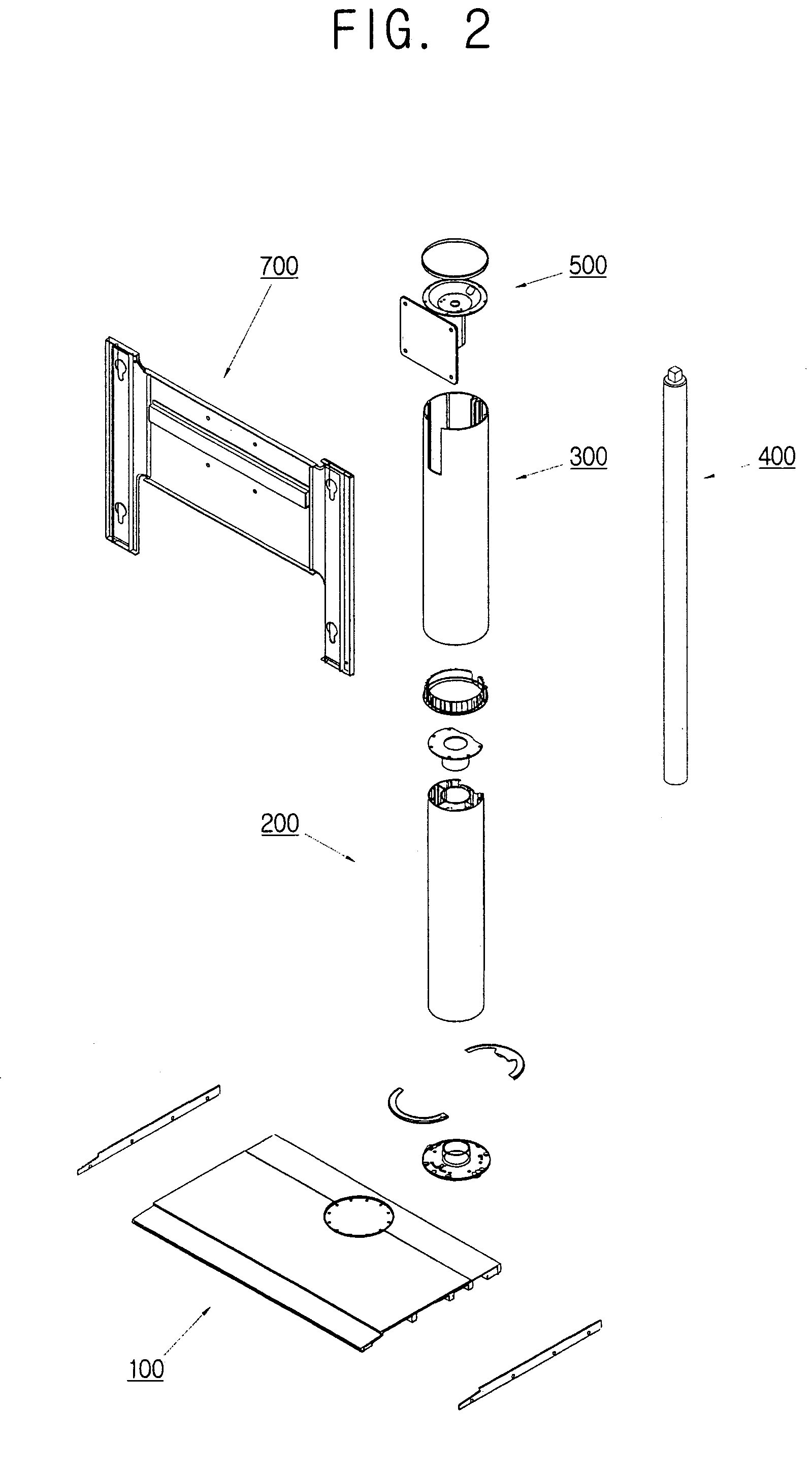
[0037]A first embodiment of the stand includes a base 100, a supporting case 200, a supporting member 400 that can be swiveled, and an mounting bracket 500. As shown in FIGS. 1 and 2, a second embodiment of the stand includes a rotating case 300 in addition to the components of the first embodiment of the stand described above. According to a third embodiment, the stand includes a display-mounting part 700 in addition to the components of the second embodiment of the stand. The display-mounting part 700 mounts on the mounting bracket 500.

[0038]Further, substituting the cylinder part 600 (see FIG. 3G) for the supporting member 400 employed in the first, second, and third embodiments, creates respective fourth, fifth, and sixth embodiments. Detailed descriptions of each embodiment shall be made with reference to FIGS. 3A through 3G, respectively, which illustrate the components of the stand.

[0039]FIG. 3A is an exploded perspective view of the base 100 of the stand according to the fir...

Example

[0054]The inserting part 550 is needed in the second embodiment described above. The inserting part 550 is a boss of predetermined thickness that corresponds to the bracket-inserting opening 330 of the rotating case 300. The boss is positioned between the engaging part 510 and the mounting face 520, and extends away from the first end of the mounting bracket 500. The inserting part 550 is inserted into the bracket-inserting opening 330.

[0055]As previously mentioned, substituting the cylinder part 600 for the supporting member 400 employed in the first, second, and third embodiments, creates fourth, fifth, and sixth embodiments In the fourth, fifth, and sixth embodiments, the distance between the base and the display can be changed and the display can also be rotated.

[0056]Referring to FIG. 3F, cylinder part 600 has a cylinder cover 610, a cylinder 620 and a bracket-engaging part 630.

[0057]According to one aspect, cylinder 620 is a hydraulic cylinder filled with gas, such as air, and...

Example

[0058]According to an aspect of the fourth embodiment, wherein the cylinder part 600 rotates, the bracket-engaging part 630 is polygonal. According to an aspect of the fifth and sixth embodiments, however, wherein the rotating case 300 rotates, the bracket-engaging part 630 is approximately cylindrical.

[0059]As shown in FIG. 3G, the display-mounting part 700 has a display base plate 710, a first engaging hole 720, a first engaging part 730, a second engaging part 740, and a second engaging hole 750.

[0060]According to the third and sixth embodiments, the display base plate 710 is shaped like a plate, and engages the mounting face 520 of the mounting bracket 500 through the first engaging hole 720 on the base plate 710 and the corresponding mounted hole 530. The first engaging part 730 and the second engaging part 740 are planar shaped wings located on opposite sides of the base plate 710, having the second engaging hole 750, through which the display is mounted to the display mountin...


PUM


Abstract

A stand for a display having a base, a supporting case mounted on the base, a supporting member mounted inside the supporting case and having an end seated on the base to support the weight of the display, and a mounting bracket engaged with the the other end of the supporting member, to mount the display. This stand supports the weight of a large-sized display and allows a user to swivel the display around an axis of the supporting member, and change the distance between the base and the display.

Description

CROSS-REFERENCE TO RELATED APPLICATIONS[0001]This application claims the benefit of Korean Patent Application No. 2002-66642, filed Oct. 30, 2002, in the Korean Intellectual Property Office, the disclosure of which is incorporated herein by reference.BACKGROUND OF THE INVENTION[0002]1. Field of the Invention[0003]The present invention relates to a stand for supporting a display that allows the display to be swiveled and elevated, and more particularly, to a stand for large-sized displays such as an LCD (Liquid Crystal Display) or a PDP (Plasma Display Panel), etc.[0004]2. Description of the Related Art[0005]Conventionally, there has been a stand that allows a display to be swiveled. This kind of conventional stand has mainly been used in lightweight small-sized stands employed for notebook computers or desktop computers. Japanese Patent Laid-Open No. 10-126068 disclosed a stand allowing the display to be swiveled. However, this type of stand cannot support heavy, large-sized display...

Claims


Application Information

Patent Timeline
IPC IPC(8): A47F5/00G06F1/16F16M11/08F16M11/28
CPCF16M11/08F16M11/28Y10S248/919G06F1/16
Inventor LEE, YOU-SUBHAN, SANG-HYUNKIM, SANG-HAK
Owner SAMSUNG ELECTRONICS CO LTD
Why Eureka
Try Eureka