Automatic sampler

a sampler and sampler technology, applied in the direction of laboratory glassware, instruments, pressure relieving devices on sealing faces, etc., can solve the problems of easy cross contamination and spread of sample peak, and achieve the effect of reducing cross contamination and volum

Active Publication Date: 2007-03-27
SHIMADZU CORP
View PDF11 Cites 20 Cited by
  • Summary
  • Abstract
  • Description
  • Claims
  • Application Information

AI Technical Summary

Benefits of technology

[0015]The present invention is developed in consideration of the problems associated with the related art. An object of the present invention is to provide an automatic sampler in which both the inner volume of a path through which a sample passes and the number of piping joints are reduced as extremely as possible.
[0017]Hence, the number of piping joints in the path through which the sample passes is reduced while dead volume is reduced, so that cross contamination is reduced.

Problems solved by technology

Hence, there is a drawback that the sample peak is spread.
In addition, if there are piping joints in the path through which the sample passes, there is generally possibility that the sample may remain in fine gaps at the piping joints so that cross contamination occurs easily.

Method used


Image

  • Automatic sampler
  • Automatic sampler
  • Automatic sampler

Examples


Embodiment Construction

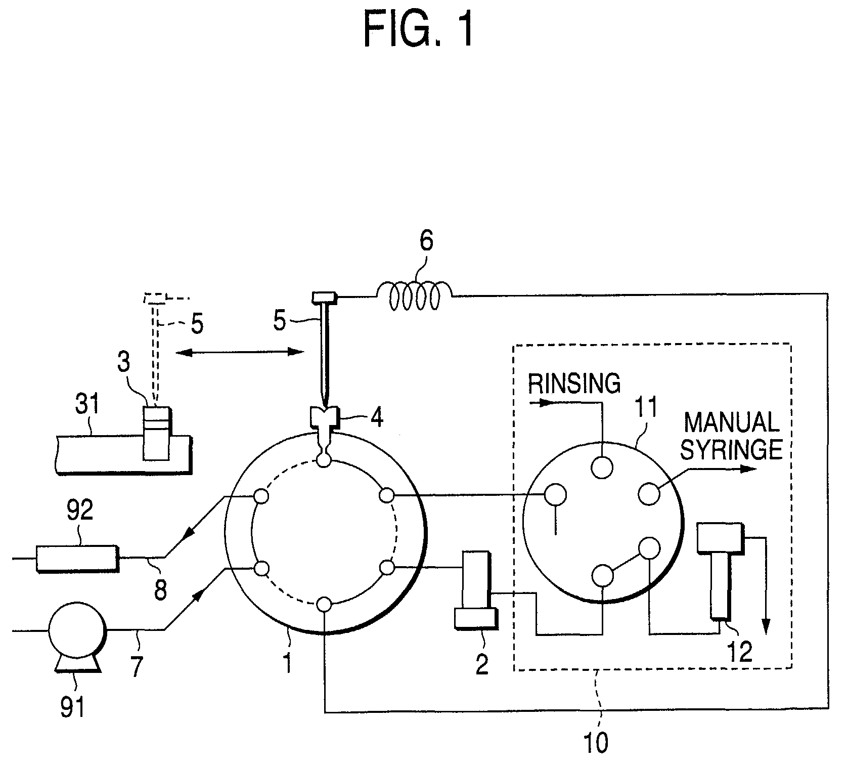
[0021]An embodiment of the present invention is shown in FIG. 1. FIG. 1 shows flow paths as important parts of a direct injection type automatic sampler according to the present invention. The embodiment shown in FIG. 1 is substantially the same as the related-art example shown in FIG. 3 except that the injection port 4 is directly connected to the flow path-switching valve 1. The operating sequence in this embodiment is the same as that in the related-art example. Constituent parts the same in function as those in FIG. 3 are referred to by numerals the same as those in FIG. 3 for the sake of omission of duplicated description.

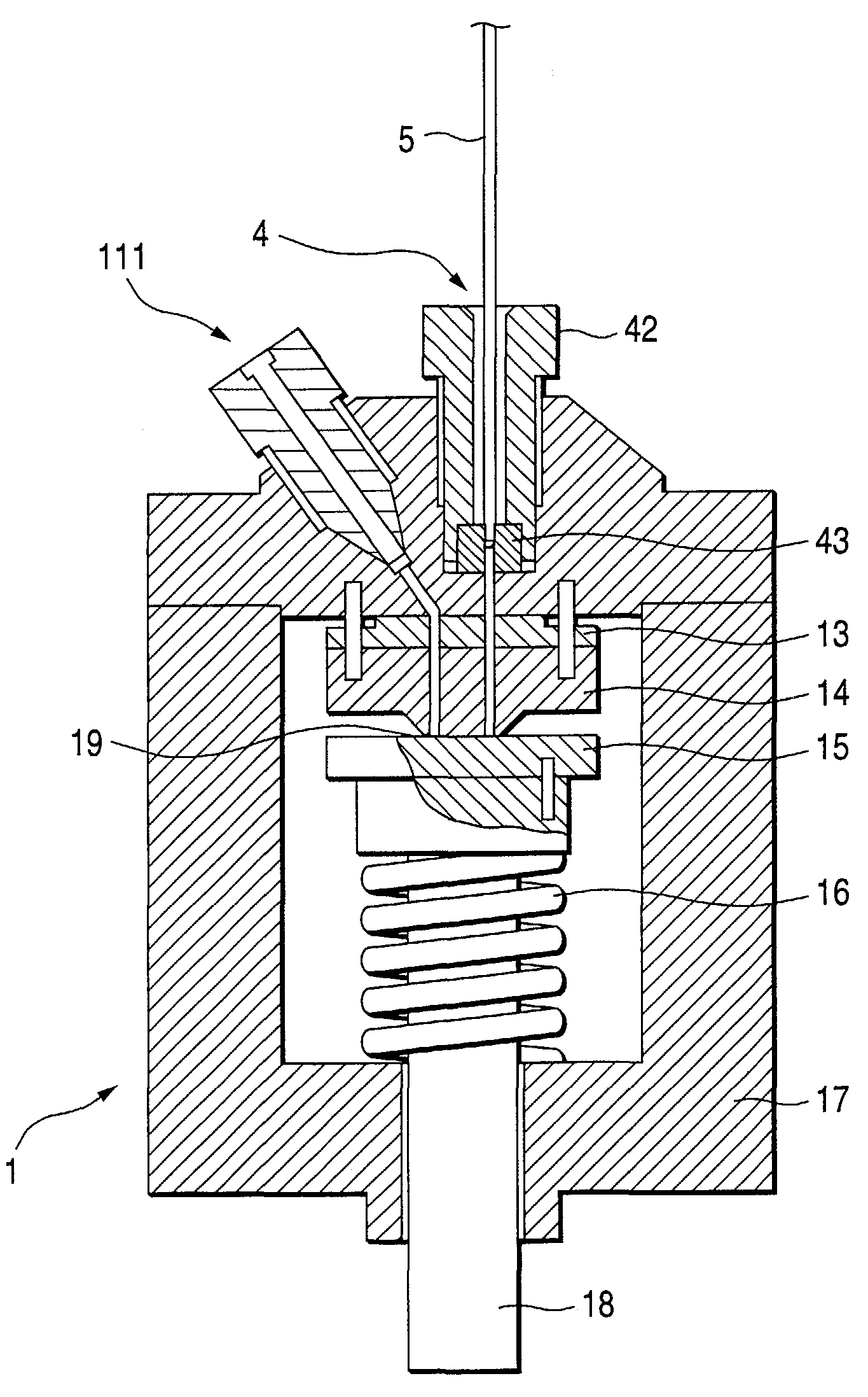
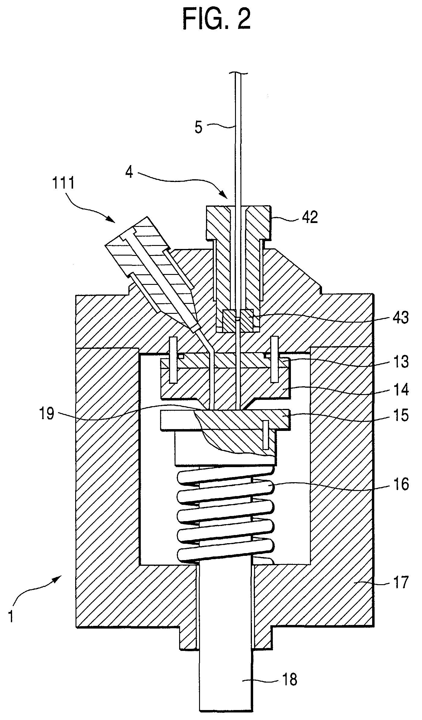
[0022]FIG. 2 is a view showing an example of specific structure of the flow path-switching valve 1 to which the injection port 4 in FIG. 1 is connected directly. The flow path-switching valve 1, the injection port 4 and the sampling needle 5 inserted into the injection port 4 are shown in FIG. 2.

[0023]The flow path-switching valve 1 has a packing 13, a stator ...


PUM

PropertyMeasurementUnit
suction forceaaaaaaaaaa
liquid sampleaaaaaaaaaa
pressureaaaaaaaaaa

Abstract

In a direct injection type automatic sampler, a sampling needle having a liquid sample collected from a sample vessel by using suction force of a pump is inserted into an injection port. Then, a flow path-switching valve is rotated to switch a flow path to make a flow of mobile phase liquid pass through a loop to thereby introduce the collected sample into a column. The injection port is directly incorporated in the flow path-switching valve.

Description

BACKGROUND OF THE INVENTION[0001]1. Field of the Invention[0002]The present invention relates to an automatic sampler, for example, an automatic sampler for introducing each sample into a liquid chromatograph automatically.[0003]2. Description of the Related Art[0004]FIG. 3 shows flow paths as important parts of a related-art automatic sampler for liquid chromatograph.[0005]In FIG. 3, an automatic sampler has a 6-port 2-position flow path-switching rotary valve 1 which has six ports arranged at regular intervals, and two path positions for connecting every adjacent two of the six ports to each other. When the flow path-switching valve 1 is rotated, one of the two path positions is moved to the other to switch flow paths.[0006]Sample vessels 3 each containing a liquid sample to be analyzed are arranged on a rack 31. A sampling needle 5 sucks in and collects the liquid sample from selected one of the sample vessels 3. The sampling needle 5 is connected to a pump 2 through both a loope...

Claims


Application Information

Patent Timeline
Patent Type & Authority Patents(United States)
IPC IPC(8): F16K1/36F16K31/00F16K39/00F16K5/00F16K5/10G01N1/00G01N30/20G01N30/24
CPCG01N30/24G01N35/1097Y10T436/11G01N2030/207Y10T137/2496Y10T137/4456Y10T137/0508Y10T137/4636
Inventor MAEDA, YOSHIAKI
Owner SHIMADZU CORP
Why Eureka
Try Eureka