Micro fluidic valves, agitators, and pumps and methods thereof

a micro fluidic valve and agitator technology, applied in the direction of valve operating means/release devices, machines/engines, positive displacement liquid engines, etc., can solve the problems of difficult to create valves with reasonably simple actuator mechanisms, difficult to create valves that seal well, and existing valve designs based on standard mems processes are prone to leakage, etc., to achieve simple actuator systems, tight seals, and wide openings.

Inactive Publication Date: 2007-03-27
ROCHESTER INSTITUTE OF TECHNOLOGY
View PDF231 Cites 35 Cited by
  • Summary
  • Abstract
  • Description
  • Claims
  • Application Information

AI Technical Summary

Benefits of technology

[0012]The present invention provides a micro fluidic valve which achieves a tight seal, has a wide opening for maximum flow, and has a simple, yet robust actuator system. Additionally, with the present invention a va

Problems solved by technology

In micro fluidics it has been very difficult to create valves that seal well.
In particular, existing designs for valves based on standard MEMS processes tend to be prone to leakage.
It has also been very difficult in micro fluidics to

Method used


Image

  • Micro fluidic valves, agitators, and pumps and methods thereof
  • Micro fluidic valves, agitators, and pumps and methods thereof
  • Micro fluidic valves, agitators, and pumps and methods thereof

Examples


Embodiment Construction

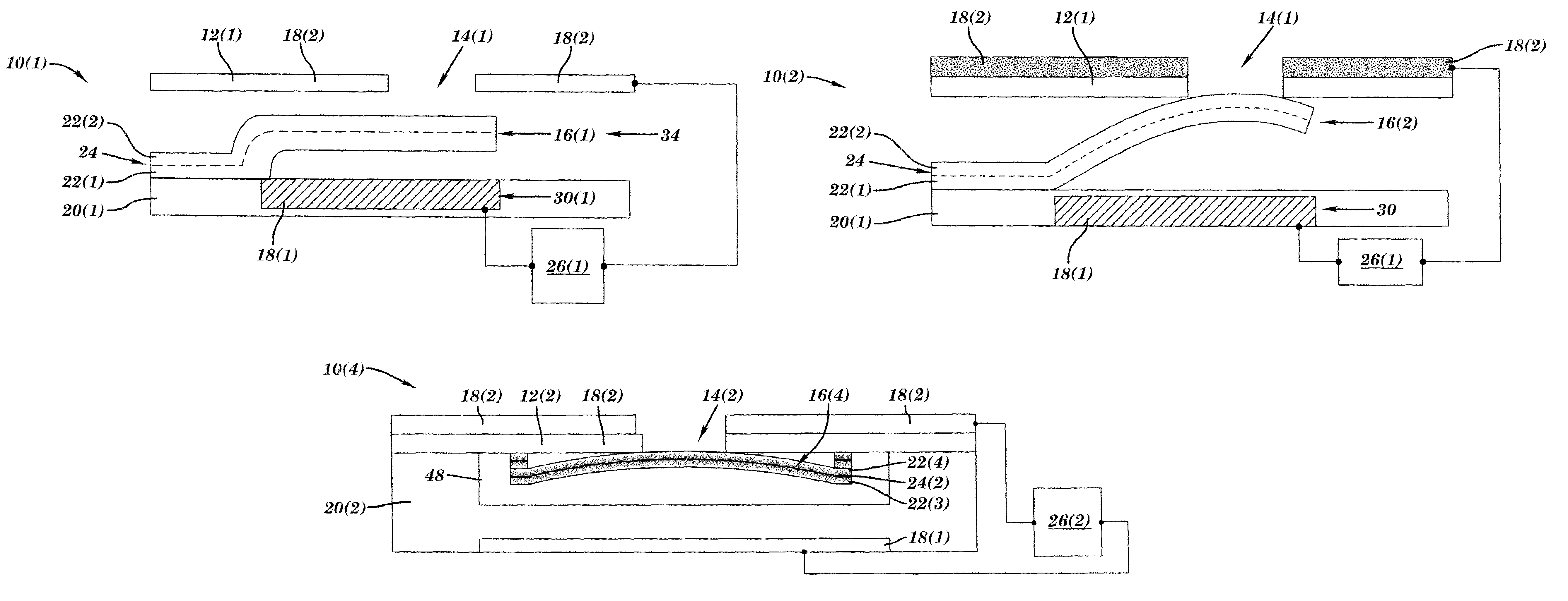
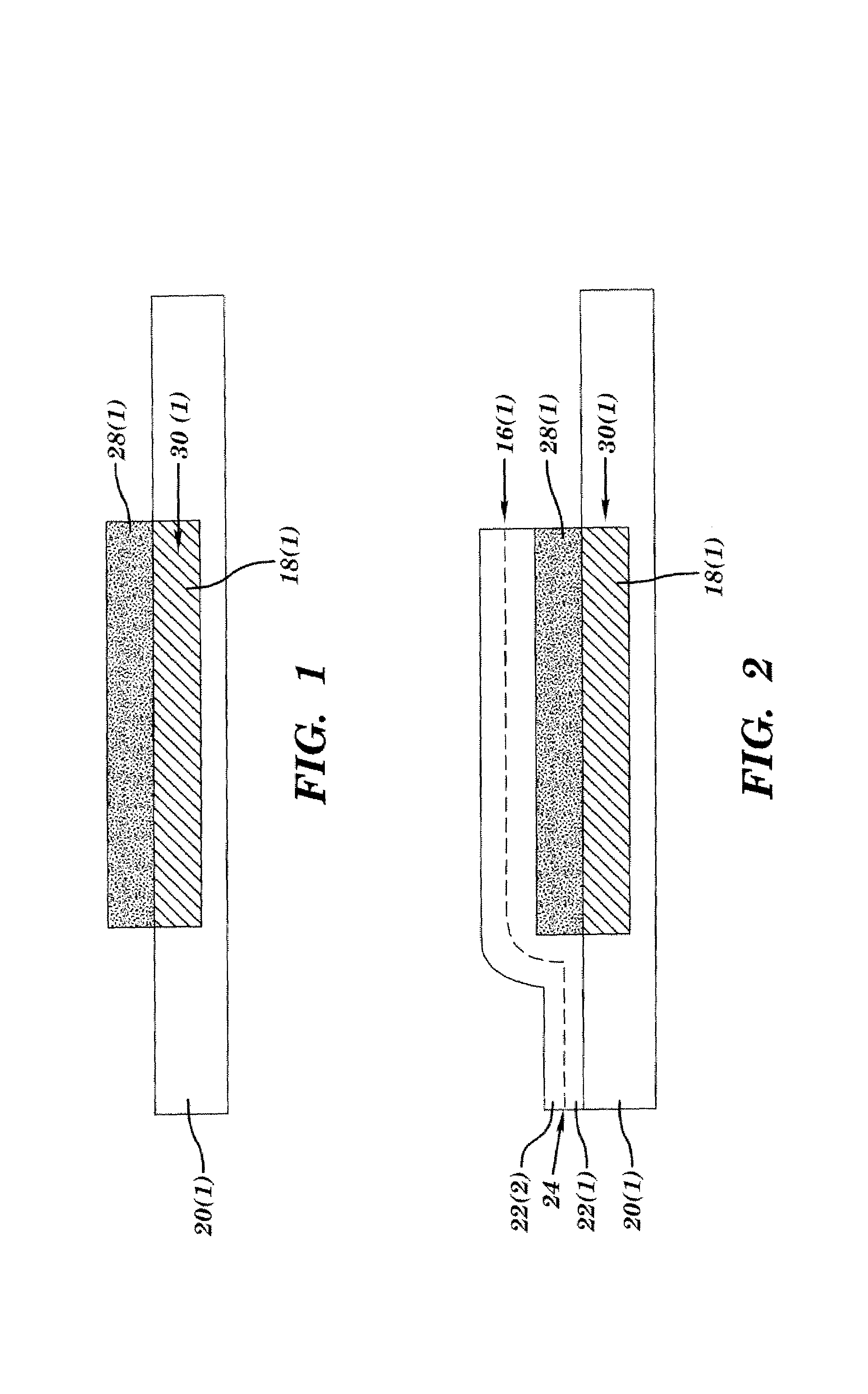
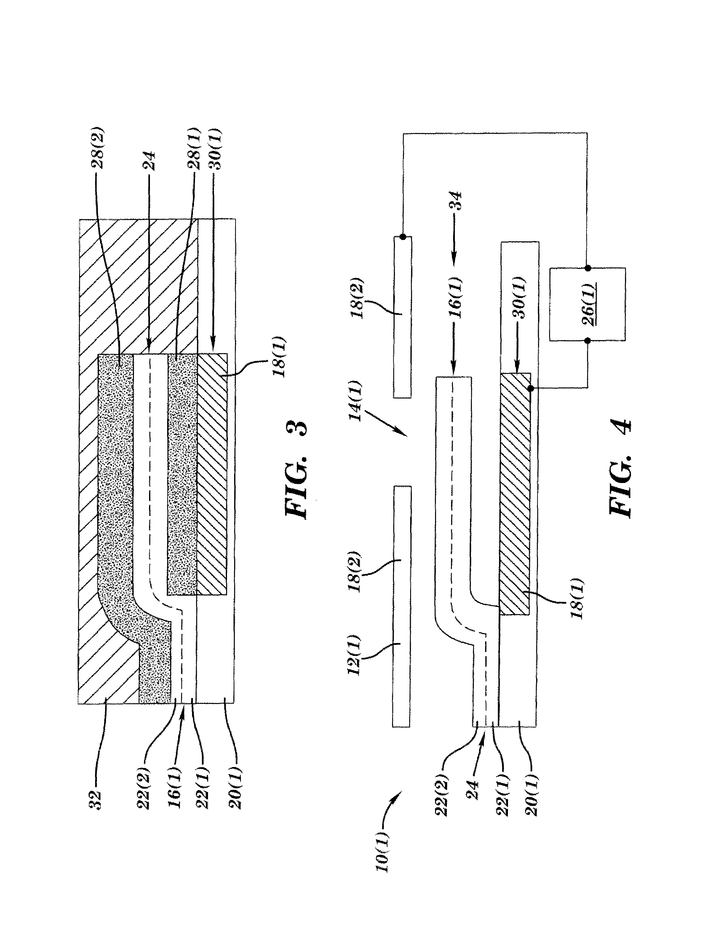
[0018]Micro fluidic devices 10(1)–10(4) in accordance with embodiments of the present invention are illustrated in FIGS. 4, 5, 10, and 11. Each of the micro fluidic devices 10(1)–10(4) include a valve seat or other structure 12(1) or 12(2) with an opening 14(1) or 14(2) and a member 16, such as a cantilever arm 16(1) or 16(2) or a membrane 16(3) or 16(4) having a fixed static charge. The member 16 has a first position exposing the opening 14(1) or 14(2) and a second position sealing the opening 14(1) or 14(2). The present invention provides micro fluidic valves which achieve a tight seal, have a wide opening for maximum flow, and have a simple, yet robust actuator system. The present invention also provides other micro fluidic devices, such as agitators and pumps.

[0019]Referring more specifically to FIGS. 4 and 5, micro fluidic devices 10(1) and 10(2), such as valves or agitators, are illustrated. Elements in FIG. 5 which are identical to those described in FIGS. 1–4, will have like...


PUM

PropertyMeasurementUnit
Structureaaaaaaaaaa
Electric chargeaaaaaaaaaa
Perimeteraaaaaaaaaa

Abstract

A valve which has a structure with at least one opening and a member which has a fixed static charge and also has a first position exposing the opening and a second position sealing the opening. A method for making the valve includes providing a structure with at least one opening and providing a member having a fixed static charge where the member has a first position exposing the opening and a second position sealing the opening. An agitator includes a base with at least one trench, a structure with at least one opening, and a membrane with a fixed static charge. The structure is connected to the base over the trench with the opening in the structure extending through to the trench in the base. The membrane is connected to the base across at least a portion of the trench. A pump includes a base with at least one trench, a structure with at least two openings, a membrane with a fixed static charge, a first cantilever arm having a fixed static charge, and a second cantilever arm having a fixed static charge. The structure is connected to the base over the trench with the openings in the structure extending through to the trench in the base. The membrane is connected to the base across at least a portion of the trench. The first cantilever arm has a first position exposing one of the openings and a second position sealing the one of the openings. The second cantilever arm has a first position exposing another one of the openings and a second position sealing the another one of the openings.

Description

[0001]The present invention claims the benefit of U.S. Provisional Patent Application Ser. No. 60 / 294,912, filed May 31, 2001, which is hereby incorporated by reference in its entirety.FIELD OF THE INVENTION[0002]This invention relates to micro fluidic valves, agitators, and pumps and methods thereof.BACKGROUND OF THE INVENTION[0003]In micro fluidics it has been very difficult to create valves that seal well. In particular, existing designs for valves based on standard MEMS processes tend to be prone to leakage.[0004]It has also been very difficult in micro fluidics to create valves with a reasonably simple actuator mechanisms. As a result, the valves are complicated to open and close as well as to manufacture.[0005]Further, it has been difficult in micro fluidics to create agitators and high force pumps.SUMMARY OF THE INVENTION[0006]A valve in accordance with one embodiment of the present invention includes a structure with at least one opening and a member having a fixed static ch...

Claims


Application Information

Patent Timeline
IPC IPC(8): B01F11/00B01F13/00F04B19/00F16K15/16F16K31/02F04B43/04F15C5/00F16K99/00
CPCF04B43/043F15C5/00F16K99/0001F16K99/0015F16K99/0051F16K99/0007F16K2099/0094F16K2099/008
Inventor POTTER, MICHAEL D.
Owner ROCHESTER INSTITUTE OF TECHNOLOGY
Why Eureka
Try Eureka