Gundrill

a technology of flutes and cutting edges, applied in the field of flutes, can solve the problems of clogging of flutes with metal chips, and the normal twist drills with two or more cutting edges extending generally outward from a central axis would not work effectively,

Inactive Publication Date: 2007-03-27
FORD GLOBAL TECH LLC
View PDF34 Cites 21 Cited by
  • Summary
  • Abstract
  • Description
  • Claims
  • Application Information

AI Technical Summary

Benefits of technology

The present invention controls the size of the outlet section to optimize the flow of drilling fluid for chip removal, cooling, and lubricating cutting surfaces and wear paths. The outlet passage area should be less than 100 percent of the bottom space cross-sectional area, preferably less than sixty percent and most preferably less than 25 percent.

Problems solved by technology

The technical problem addressed in this patent text relates to improving the efficiency and effectiveness of gundrills when drilling deep holes in various metal workpieces. Specifically, the goal is to create a new gundrill design that can easily form small chips during drilling operations, extract them quickly and efficiently using drilling fluid, and maintain optimal performance over time without requiring excessive repairs or replacement parts. Additionally, the ideal design will also allow for increased productivity and reduced downtime due to longer periods of usage between re-dressings.

Method used


Image

  • Gundrill
  • Gundrill
  • Gundrill

Examples


Embodiment Construction

)

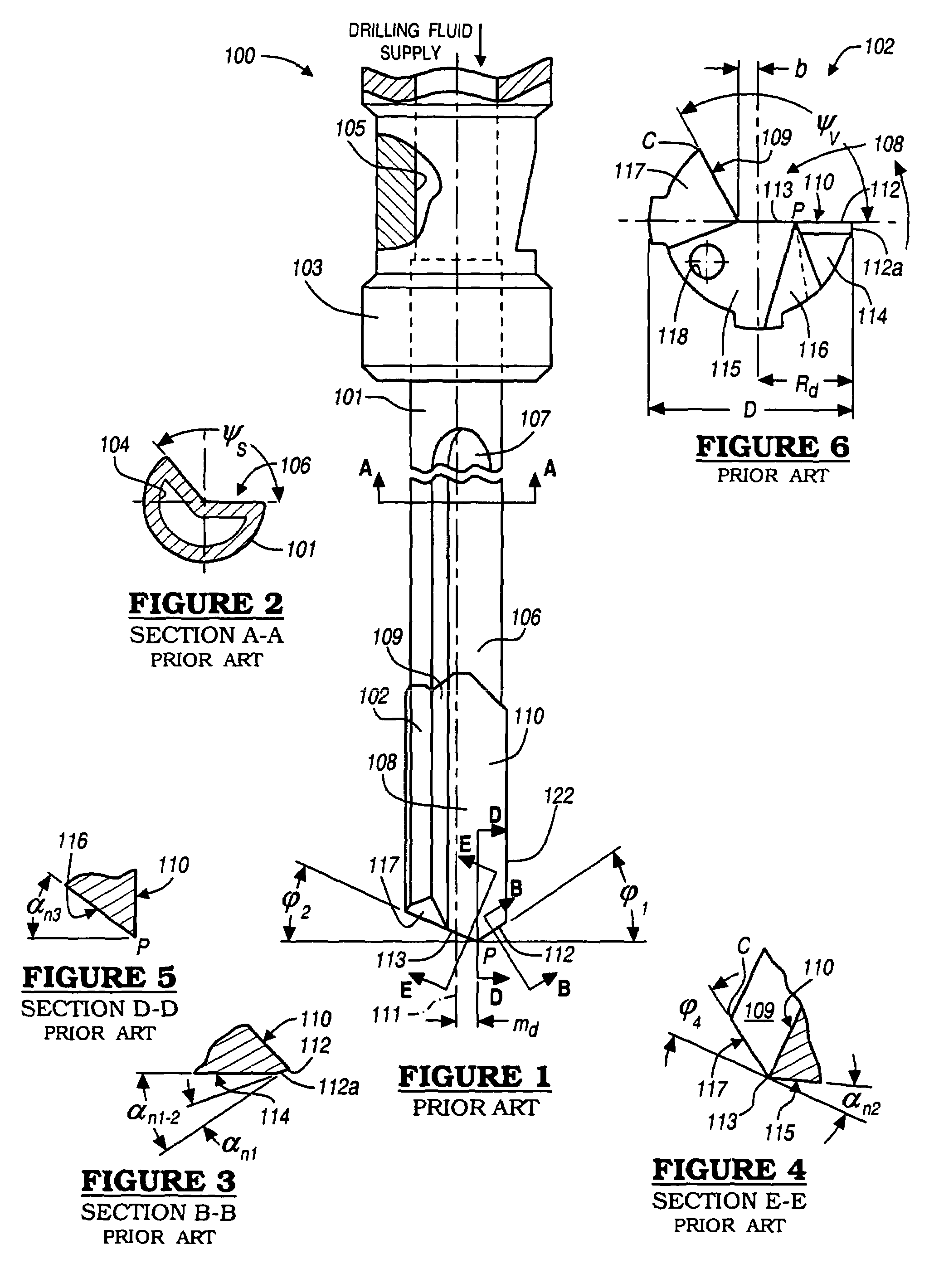
[0049]In order to understand the subtle, but dramatic differences between the present invention and the prior art, it is necessary to first understand the gundrills of the prior art, particularly how they interact with the hole being formed and the drilling fluid being supplied to the cutting tip. After a detailed analysis of chip formation and the drilling fluid flow behavior in prior art gundrills, the benefits and advantages of the present invention can be fully understood and appreciated.

[0050]Gundrilling is a method of drilling holes where a self-piloting tool with an internal drilling fluid supply and an external chip removal path is used. A commonly used gundrill 100 of the prior art is shown in FIGS. 1 through 6. Gundrill 100 consists of a drill body having a shank 101 and a tip 102. The tip 102 is mounted on the free end of the shank 101, and is made up of a hard wear-resistant material such as a metallic carbide. The other end of the shank 101 is provided with an enlarged...


PUM

PropertyMeasurementUnit
Fractionaaaaaaaaaa
Fractionaaaaaaaaaa
Fractionaaaaaaaaaa

Abstract

A method of forming deep holes and a gundrill therefore is disclosed. The gundrill has an elongate tubular shank and a cutting tip, each provided with a tubular central region supplying pressurized drilling fluid and a non-circular fluid cross-section defining a drilling fluid return path in conjunction with the hole being formed. The cutting tip flute defines a primary rake surface terminating in an offset point, and a secondary flank surface for forming an outlet with the hole being drilled, sized to maintain fluid pressure in the bottom end space to cool the cutting surfaces and to effectively remove chips as they are formed. A localized relief passage, sized relative to the outlet passage to cause a significant amount of drilling fluid to flow therethrough, is formed behind a peripheral rake edge of the primary rake surface for drilling fluid to exit the end space and cool the tip.

Description


Claims


Application Information

Patent Timeline
Owner FORD GLOBAL TECH LLC
Why Eureka
Try Eureka