
Graduated stiffness for electrical connections in tires

a technology of electrical connections and tires, applied in the direction of fixed connections, coupling device connections, printed circuit assembling, etc., can solve the problems of b>20/b> being likely to suffer a fatigue failure (or break), affecting and affecting the service life of the circuit. , to achieve the effect of enhancing the stress resistance of the circui

Inactive Publication Date: 2007-03-27
MICHELIN NORTH AMERICA
View PDF28 Cites 8 Cited by
  • Summary
  • Abstract
  • Description
  • Claims
  • Application Information

AI Technical Summary

Benefits of technology

"The present invention provides an electrical connection that is resistant to mechanical stresses caused by bending or twisting of wires or leads. This is achieved by creating a region of decreasing flexibility or graduated stiffness near the point of connection to the circuit, which allows for a greater distribution of stress over the end of the lead and into the surrounding material. The connection can be created using stress distributing materials or specialized mechanical connection methodologies. The invention also provides a durable connection that includes a substrate supporting at least a portion of the electrical circuit and a conductor that is embedded within a material for distributing stress. The material for distributing stress is bonded to the printed circuit board so as to provide an electrical connection that is substantially immovable relative to the circuit. The invention can be used in various applications such as in the automotive industry, where electrical connections are often subjected to mechanical stresses."

Problems solved by technology

In circumstances where the wire and the connected-to circuit may move or rotate relative to one another, the wire may incur a concentration of mechanical stress and / or fatigue at or near the point of connection to the circuit.
Mechanical stresses such as repeated bending or twisting, for example, can lead to a weakening of the wire until a break occurs.
As a result, lead 20 will likely suffer a fatigue failure (or break) either at or near point of connection 26.

Method used


Image

  • Graduated stiffness for electrical connections in tires
  • Graduated stiffness for electrical connections in tires
  • Graduated stiffness for electrical connections in tires

Examples


Embodiment Construction

[0019]Reference will now be made in detail to embodiments of the invention, one or more examples of which are illustrated in the drawings. Each example is provided by way of explanation of the invention, and not meant as a limitation of the invention. For example, features illustrated or described as part of one embodiment can be used with another embodiment to yield still a third embodiment. It is intended that the present invention include these and other modifications and variations.

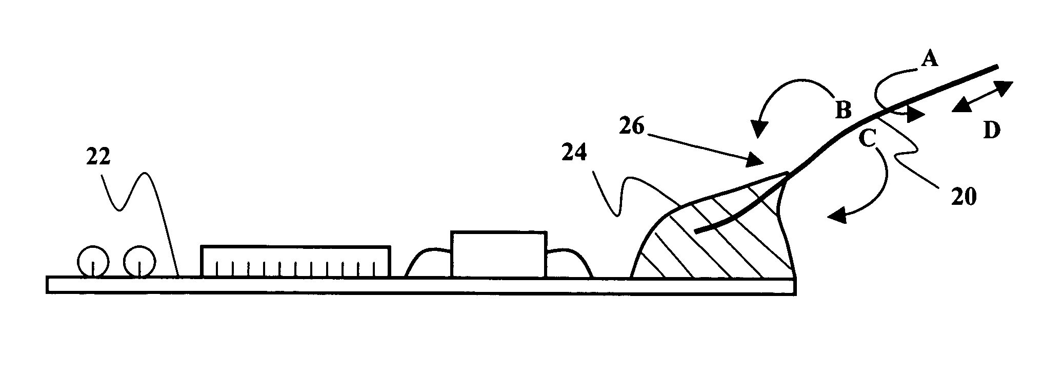
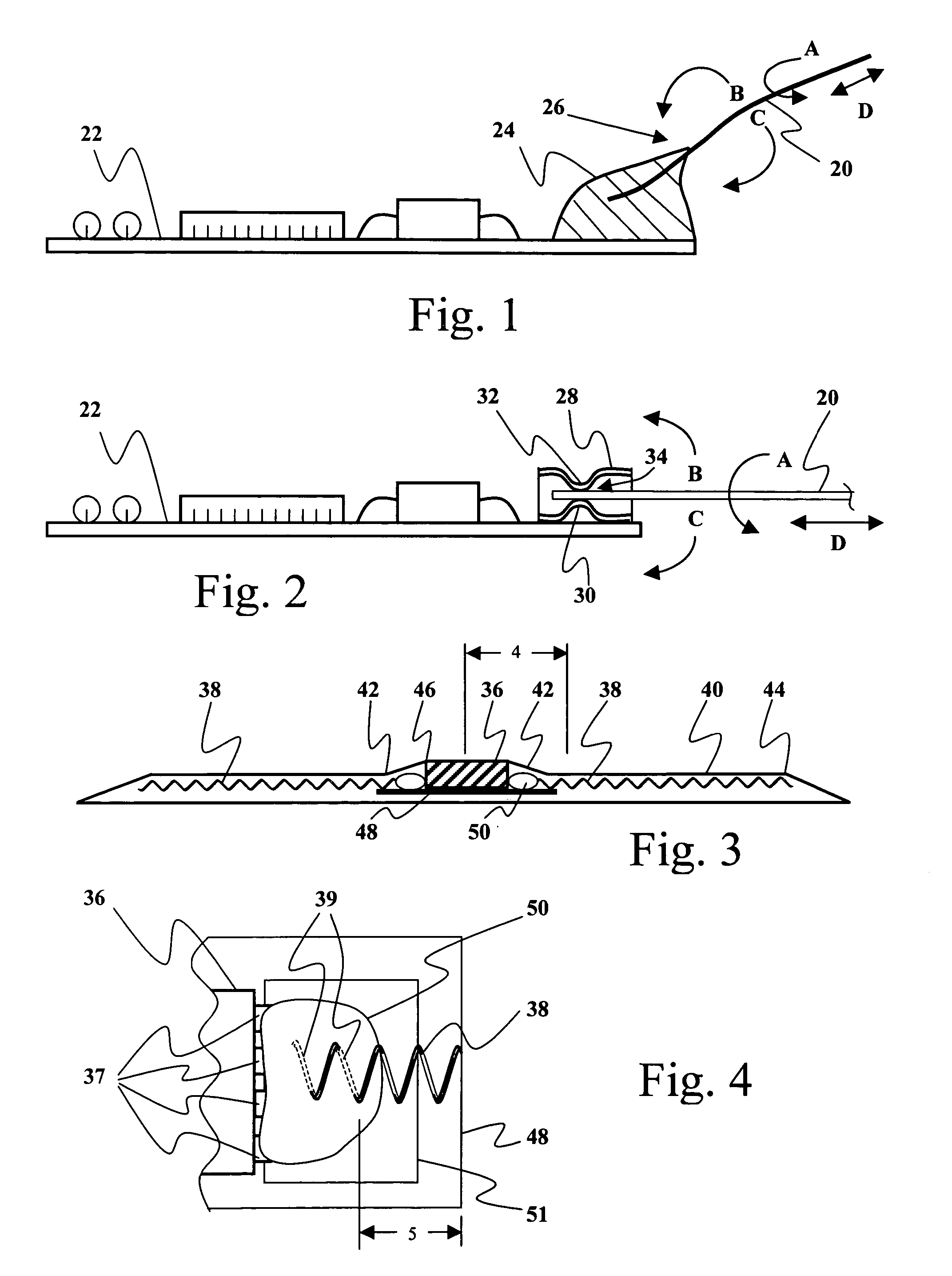
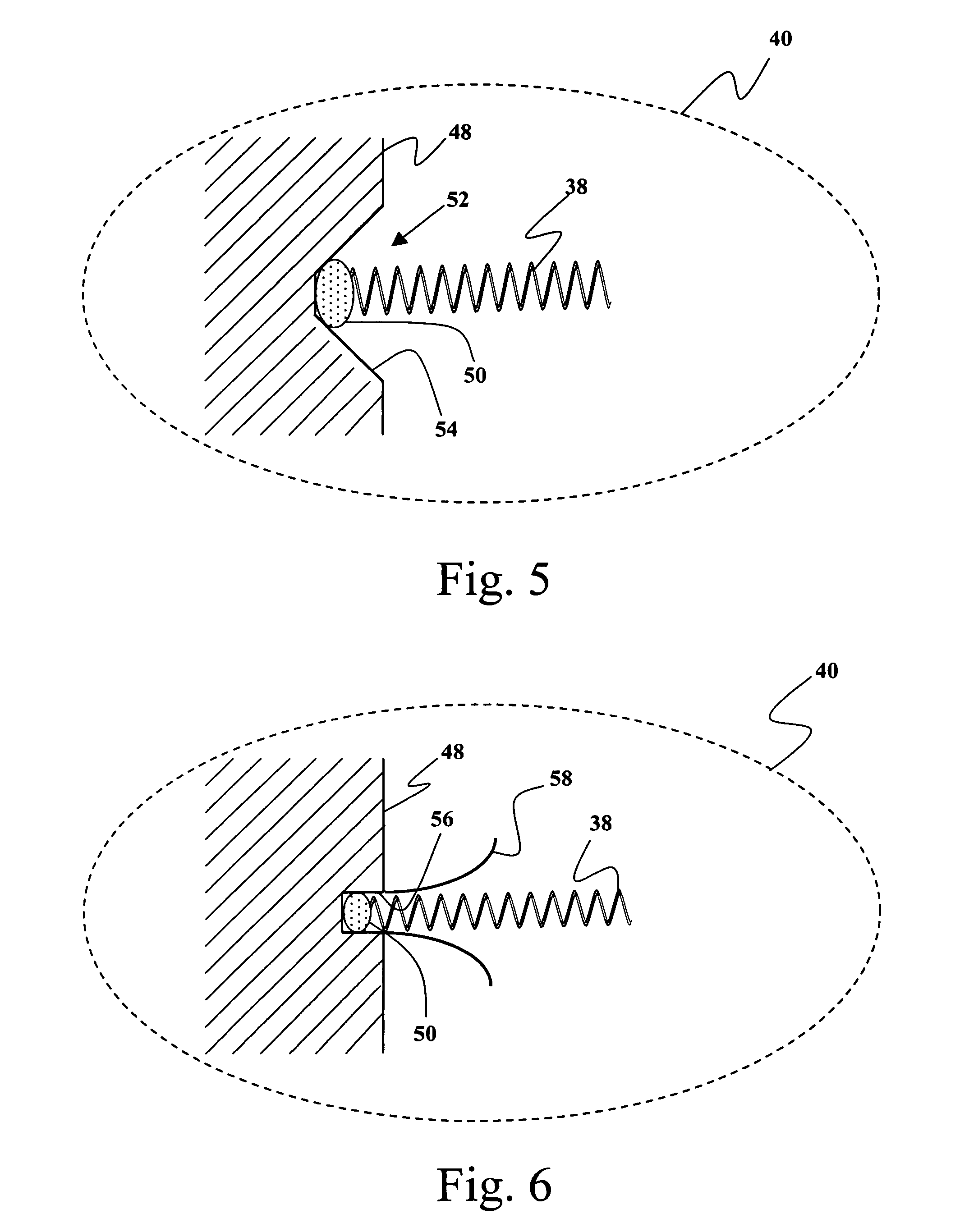
[0020]FIGS. 3 and 4 provide side cross-section and partial plan illustrations respectively of an exemplary embodiment of the present invention. The particular illustrations represent a tire patch as might be used to house tire electronics for mounting in association with a tire. As shown, an exemplary tire electronics circuit element 36 is mounted on printed circuit board 48 and the combination is encased in an elastomeric tire patch 40. In this embodiment, electrical conductors 38 are connected to ci...


PUM


Abstract

A strain-resistant electrical connection and a method of making the same is provided. A wire or other conductive lead is connected to a circuit in a manner that makes the connection more resistant to mechanical stresses such as movement or rotation of the lead relative to the circuit. A material is configured around the lead and near the point of connection to the circuit so as to create a region of decreasing flexibility or graduated stiffness near the point of connection. In certain embodiments, the lead may also be coiled or otherwise shaped to provide additional ability to withstand mechanical stresses. In other embodiments, additional elements may be provided to assist in controlling the stiffness near the connection point.

Description

CROSS-REFERENCE TO RELATED APPLICATIONS[0001]The present application is a continuation-in-part of U.S. patent application Ser. No. 10 / 827,593, filed Apr. 19, 2004, entitled STRAIN-RESISTANT ELECTRICAL CONNECTION, to which Applicants claim priority.TECHNICAL FIELD OF THE INVENTION[0002]The present invention relates to a strain or fatigue-resistant electrical connection and a method of making the same. More specifically, the present invention provides for a connection between a lead and a circuit in a manner that makes the connection more resistant to damage caused by mechanical stresses such as movement or rotation of the lead relative to the circuit. In the present invention, a material is configured around the lead so as to create a region of decreasing flexibility or graduated stiffness near the point of connection. In certain embodiments, the lead may also be coiled or otherwise shaped to provide additional ability to accommodate mechanical strain without failure.BACKGROUND OF TH...

Claims


Application Information

Patent Timeline
Patent Type & Authority Patents(United States)
IPC IPC(8): B60C23/00B60C23/04H05K7/00H01R4/02H01R4/20H01R13/58H01R43/02H02G11/00H05K3/30H05K3/34
CPCH01Q1/2241H01Q1/40H01R4/02H01R4/20H01R12/53H01R13/58H01R43/0256H05K3/301B60C23/0493B29D2030/0072H05K2203/1194H01R13/5808H01R13/5845H01R2201/02H01R2201/26H05K3/305H05K3/3421H05K2201/0133H05K2201/10265H05K2201/10287B60C23/00
Inventor SINNETT, JAY C.MYATT, DAVID J.METCALF, ARTHUR R.
Owner MICHELIN NORTH AMERICA
Learn More