Distance-measuring system

a distance-measuring system and laser beam technology, applied in the direction of distance measurement, instruments, using reradiation, etc., can solve the problems of difficult laser beam projection to the prism, unsuitable for long distance measurement, and not very economical to provide a distance-measuring system for long distance. , to achieve the effect of simple system design

Active Publication Date: 2007-03-27
KK TOPCON
View PDF4 Cites 55 Cited by
  • Summary
  • Abstract
  • Description
  • Claims
  • Application Information

AI Technical Summary

Benefits of technology

[0014]It is an object of the present invention to provide a distance-measuring system, in which it is possible to carry out d

Problems solved by technology

As described above, the beam diameter of the laser beam is small in the non-prism distance-measuring system, and it is difficult to project the laser beam to the prism.
Accordingly, this is not suitable for the measurement of long distance by using a prism.
However, it is not very economical to pr

Method used


Image

  • Distance-measuring system
  • Distance-measuring system
  • Distance-measuring system

Examples


first embodiment

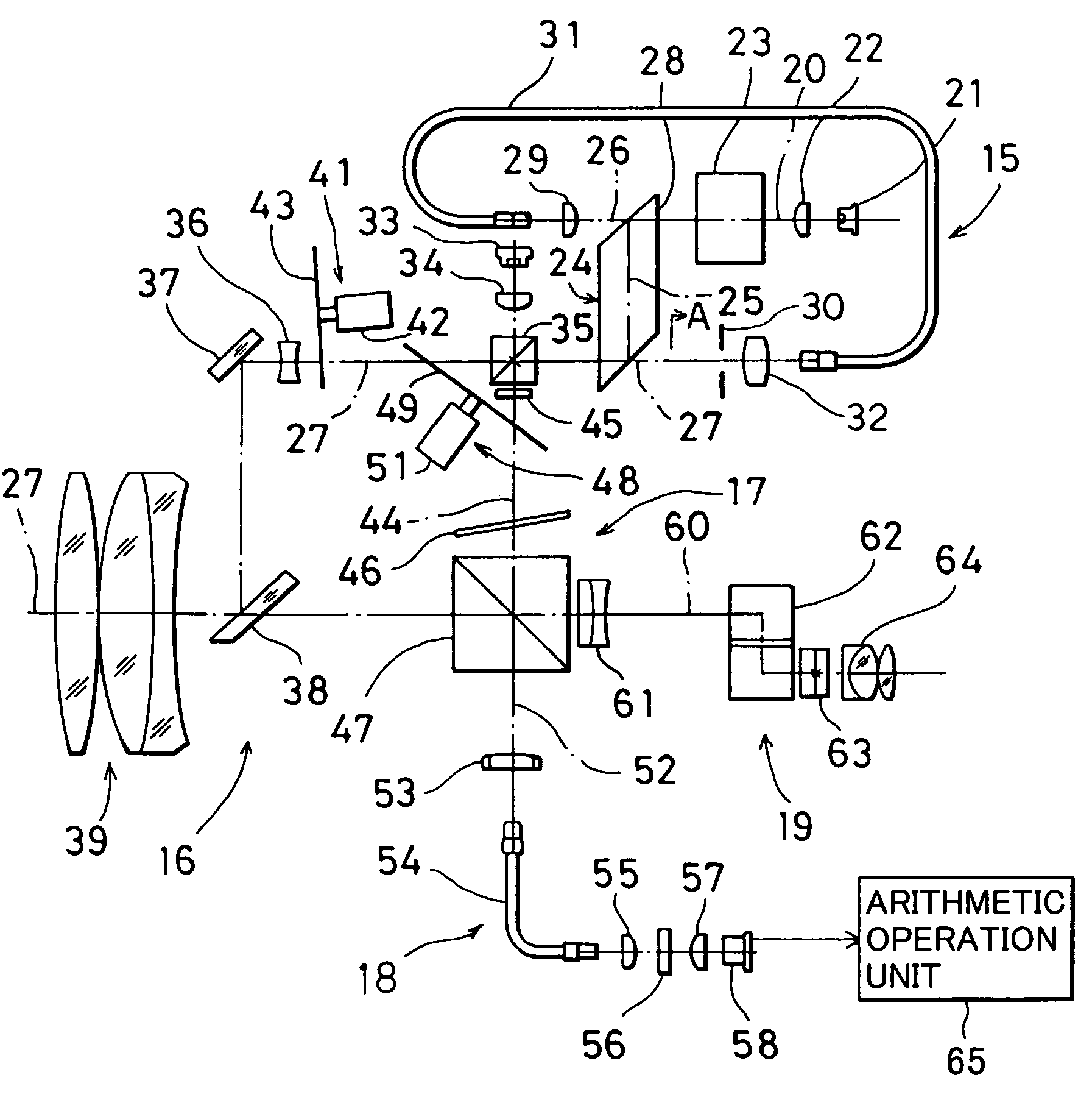
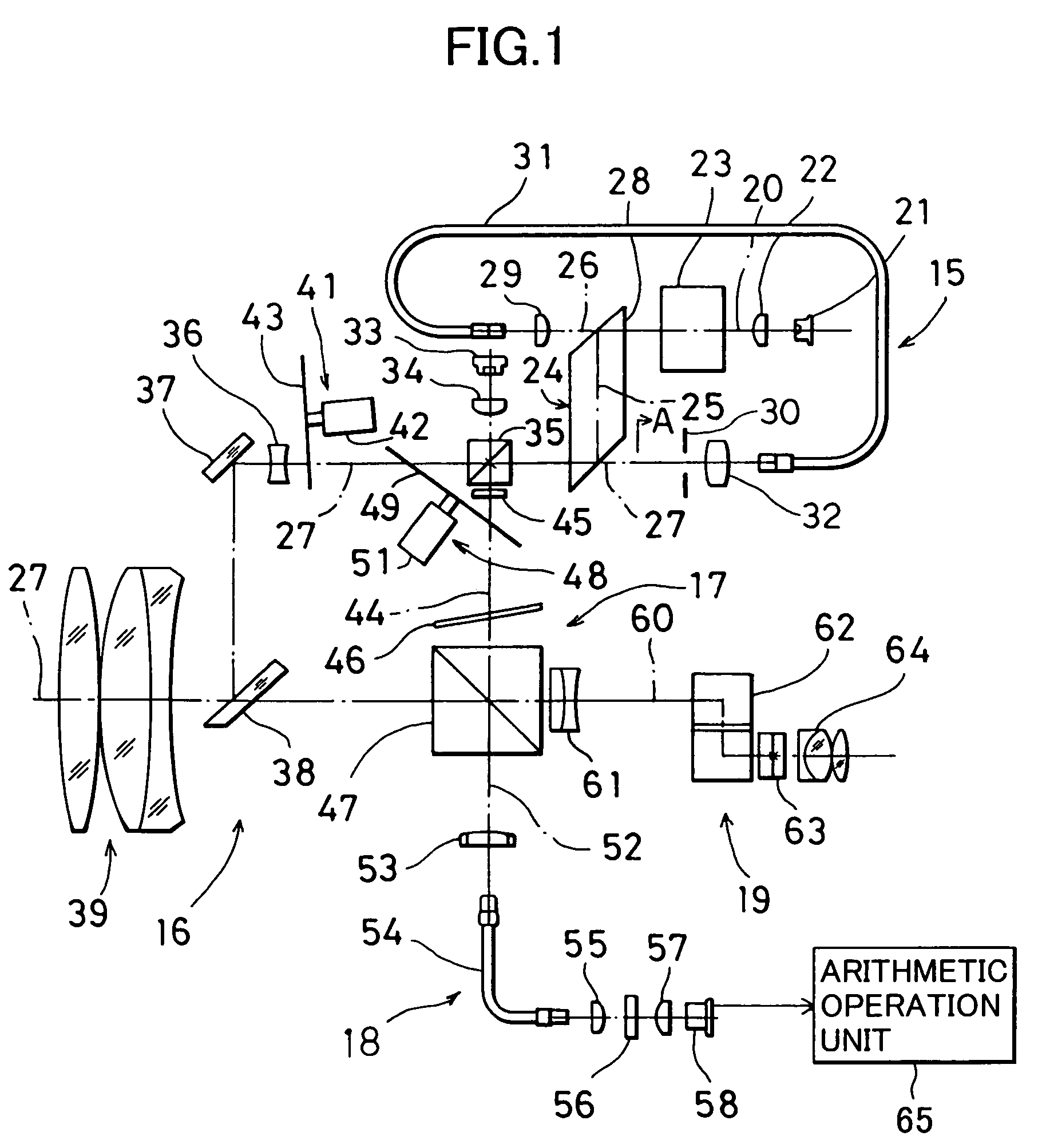
[0023]FIG. 1 is a schematical block diagram of a first embodiment according to the present invention. In the figure, reference numeral 15 denotes a light source unit, 16 is a projecting optical system, 17 is an internal reference optical system, 18 is a photodetection optical system, and 19 is an ocular optical system (telescope).

[0024]First, description will be given on the light source unit 15.

[0025]A laser light source 21 emits an infrared distance-measuring light with a wavelength of 780 nm, for instance. On an optical axis 20 of the laser light source 21, there are provided a first collimator lens 22, a mixing means 23, and an optical path switching means 24.

[0026]As the mixing means 23 as described above, means disclosed in JP-A-2002-196076 is used, for instance.

[0027]The mixing means 23 described in JP-A-2002-196076 has a pair of gradient index lenses provided on the optical axis and a phase plate placed between the gradient index lenses to shut off the optical path so that t...

second embodiment

[0076]FIG. 5 shows the present invention.

[0077]In the second embodiment, such a case is shown that a light source for the prism measurement and a light source for the non-prism measurement are provided separately from each other. FIG. 5 shows a light source unit 15, and the other arrangement is the same as shown in FIG. 1, and detailed description is not given here.

[0078]On an optical axis 20, there are provided a laser light source 21 as a light source for non-prism measurement, a first collimator lens 22, a mixing means 23, and a beam splitter 74. On a second optical path 26 perpendicularly crossing the optical axis 20 at the beam splitter 74, there are provided an auxiliary laser light source 75, an auxiliary first collimator lens 76, an auxiliary mixing means 77, a second collimator lens 29, an optical fiber 31, and a third collimator lens 32. It is designed in such manner that an auxiliary distance-measuring light emitted from the auxiliary laser light source 75 enters the beam...


PUM


Abstract

A distance-measuring system, which comprises a light source unit for emitting a distance-measuring light, a photodetection optical system having a photodetection optical axis, a projecting optical system having a projecting light optical axis and for projecting the distance-measuring light from the light source unit to an object to be measured and for guiding the distance-measuring light reflected from the object to be measured toward the photodetection optical system, and an internal reference optical system for guiding the distance-measuring light from the light source unit to the photodetection optical system as an internal reference light, wherein the light source unit can emit two distance-measuring lights with different spreading angles, and one of the light source unit and the projection optical system has a decentering member for decentering the distance-measuring light with respect to the projecting light optical axis.

Description

BACKGROUND OF THE INVENTION[0001]The present invention relates to a distance-measuring system for measuring a distance to an object by using a laser beam.[0002]In recent years, a non-prism distance-measuring system, a distance to an object to be measured is measured by directly projecting a laser beam for distance measurement to the object to be measured.[0003]In the non-prism distance-measuring system, a laser beam with a smaller beam diameter is used. By using the laser beam with a smaller beam diameter, the laser beam can be projected to the object to be measured by pinpoint. A measuring position on the object can be clearly defined, and it is possible to measure a crest line or a specific point of the object to be measured.[0004]Because an intensity of the projected laser beam is limited from reasons such as safety, in the non-prism distance measuring system, in which high reflection from the object to be measured cannot be expected, the measured distance is shorter compared wit...

Claims


Application Information

Patent Timeline
IPC IPC(8): G01C5/00G01C3/06G01C15/00G01S7/48G01S7/481G01S7/497G01S17/08
CPCG01C15/002G01S7/4811G01S7/497G01S7/4818G01S7/4812
Inventor OHTOMO, FUMIOKODAIRA, JUN-ICHI
Owner KK TOPCON
Why Eureka
Try Eureka