Crash sensor systems utilizing vehicular inertial properties

a sensor system and vehicle inertial property technology, applied in the field of electronic crash sensor systems, can solve the problems of increasing the increasing the cost and complexity of the accelerometer and sensor software design, and the mechanical structure of the accelerometer to change geometrically as a function of time and/or temperature, etc., to achieve the effect of simplifying the system design, reducing the loss of inertial device accuracy, and improving the accuracy of position chang

Inactive Publication Date: 2014-12-16
AUTOMOTIVE TECH INT
View PDF35 Cites 24 Cited by
  • Summary
  • Abstract
  • Description
  • Claims
  • Application Information

AI Technical Summary

Benefits of technology

[0015]The changes to the mechanical properties of the MEMS devices due to aging and temperature generally act slowly. The properties of the inertial devices, therefore, do not change rapidly and thus if the vehicle enters a zone of poor GPS reception, there is little loss in accuracy of the inertial devices until GPS reception is restored even if this takes several minutes. This method of correction of the inertial devices is believed to be considerably more accurate than the standard self-test methods used by conventional airbag crash sensors. Additionally, since changes in the atmospheric disturbances of the GPS signals are also occur slowly, differential corrections are not required, similarly simplifying the system design. Although there may be significant errors in the actual displacements due to such effects, the change in these displacements from one instance of GPS reception to another, later instance of GPS reception, separate by a period of lack of GPS reception, are quite accurate.
[0016]To use GPS to correct the IMU accelerometers and gyroscopes, accurate absolute positioning is not required, since it is the change in position as measured by the GPS and IMU that will be compared. Thus, differential corrections are not needed. However, the accuracy of this position change is valuable and thus the change in the phase of the carrier frequency from one reception to another can be used. This allows a measurement accuracy of a centimeter or better. To use this concept for angular displacements, three or more antennas with a separation between any pair of at least a few centimeters can be used, e.g., with a separation from about 1 to about 10 centimeters or more.
[0017]Although various numbers of inertial devices can be effectively used with this invention, at significantly less than $1 per accelerometer, little cost penalty is incurred by using more rather than fewer devices. The computational complexity is minimal since the computations do not need to be carried out frequently and a common microprocessor can be used for both the GPS and inertial device computations. In some implementations, additional devices such as a temperature sensor or additional accelerometers tuned to different sensitivity ranges can be added in order to improve the crash sensing capabilities of the system and also render the device useful for other applications, such as navigation and electronic stability control. Accelerometers are now available where the range is dynamically settable so that the same accelerometer can be used at one time for navigation and at another time for crash sensing. Various versions of the Kalman filter or neural network can be used to couple the GPS and IMU systems together as will be discussed below. In some cases, a trained neural network can be used to supplement a Kalman filter rather than as a substitute therefor.
[0018]Generally, a GPS employs a single receiving antenna. In such an implementation, the location of a point coincident with the antenna can be calculated. To determine the angular orientation of the vehicle, additional antennas can be used at little additional cost. A combination of three antennas, for example, will provide angular orientation information as well as position information. Multiple antennas also provide the opportunity of providing some correction of multipath effects as is known by those skilled in the art, and for more accurate angular motion determination as discussed above.
[0019]In a preferred implementation, the power requirements of the system are sufficiently low that significant drain on the vehicle battery will be avoided. Thus, in a preferred implementation of the invention the GPS and IMU system will be always on. If the vehicle is not moving for a significant time period, the devices can be placed in a sleep mode and awakened on any significant motion. Although this system is primarily intended for crash and rollover sensing, a sufficiently inexpensive device can be replicated at various other locations in the vehicle to be used for such tasks as electronic stability control or navigational purposes. Alternatively, a single system can provide the required information for electronic stability control, navigation as well as crash and rollover sensing.

Problems solved by technology

The silicon crystal typically has residual stresses that can cause the mechanical structure of the accelerometer to change geometrically as a function of time and / or temperature unpredictably.
This adds cost and complexity to the accelerometer and sensor software design.
This self-testing feature also increasingly complicates the device design if more than one axis is simultaneously tested.

Method used


Image

  • Crash sensor systems utilizing vehicular inertial properties
  • Crash sensor systems utilizing vehicular inertial properties
  • Crash sensor systems utilizing vehicular inertial properties

Examples


Embodiment Construction

1. Introduction

[0042]An object of the present invention is to provide an IMU crash and rollover sensor. To do this, the basic engineering solutions for a GPS-corrected IMU crash and rollover sensor primarily for low-price mass produced cars is presented herein. This objective is accomplished by:

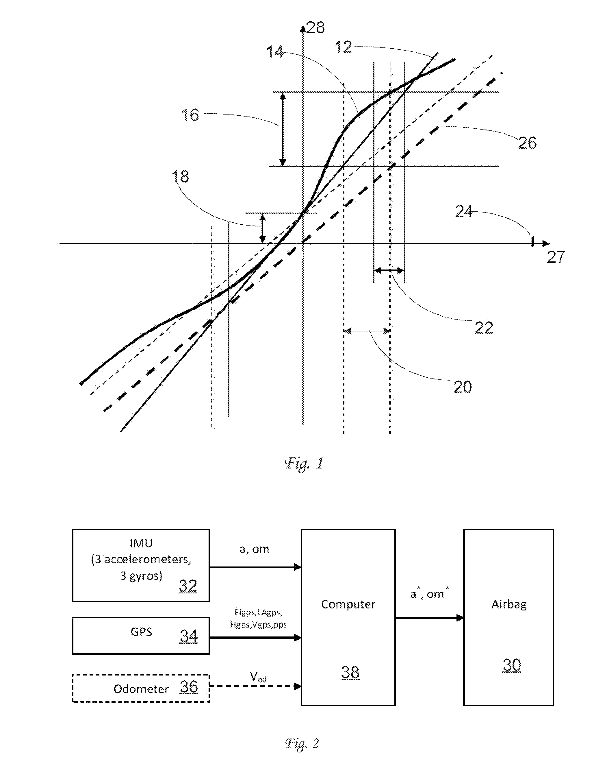
[0043]1) Using the Airbag lumped control circuit, the airbag ECU, comprising a control system with an inertial measurement unit, IMU, mounted at a central sensing point instead of the currently widely used distributed sensors and circuit for mounting crash sensors at the expected impact points of the vehicle. This currently standard system involves expensive and unreliable communication lines and connectors for transmitting signals to the central decision-making unit.

[0044]2) Manufacturing IMUs in accordance with the mass-production MEMS technology at a cost of a few dollars per unit. An IMU can comprise 3 accelerometers and 3 gyroscopes or more generally, a plurality of accelerometers and / or...


PUM


Abstract

Electronic crash sensor system for a vehicle including at least one inertial measurement device arranged on the vehicle to measure an inertial property of the vehicle, a processor that incorporates or executes a crash sensing algorithm that determines whether the vehicle is sensing a crash based on the inertial property measured by each inertial measurement device and a positioning system arranged on the vehicle to provide its position. The inertial property measured by each inertial measurement device is modified based on the position and then provided to the crash sensing algorithm such that the crash sensing algorithm determines whether the vehicle is sensing a crash based on the modified inertial property measured by each inertial measurement device. Self-testing of each inertial measurement device is not performed.

Description

FIELD OF THE INVENTION[0001]The present invention relates generally to electronic crash sensor systems for vehicles and techniques to improve the reception and processing of a crash pulse by the crash sensor system to optimize actuation of occupant protection devices, and more specifically, to techniques to improve the accuracy of the crash pulse in order to base deployment of airbags thereon.BACKGROUND OF THE INVENTIONGeneral[0002]Automobile production worldwide is exploding. As the economies in developing countries improve, the desire for automobiles by their citizens is fueling the increase automobile production worldwide. China now produces many more vehicles than the United States and is exporting many vehicles to other developing countries. With this projected vast increase in production, there is a corresponding need to significantly reduce the costs of such vehicles since they are targeted for consumers with little money. Nevertheless, purchasers of such vehicles are cogniza...

Claims


Application Information

Patent Timeline
Patent Type & Authority Patents(United States)
IPC IPC(8): B60R21/0136
CPCB60R21/0136B60R21/0132
Inventor BREED, DAVID SLEONETS, OLEXANDER
Owner AUTOMOTIVE TECH INT
Why Eureka
Try Eureka