Mehtod and system for vaporization of liquid fuels

a liquid fuel and vaporization technology, applied in the direction of combustible gas production, combustible gas purification/modification, combustible gas catalytic treatment, etc., can solve the problems of limited vaporization rate, fuel decomposition and formation of deposits, and difficulty in forming cok

Active Publication Date: 2008-06-05
PRECISION COMBUSTION
View PDF8 Cites 24 Cited by
  • Summary
  • Abstract
  • Description
  • Claims
  • Application Information

AI Technical Summary

Problems solved by technology

One disadvantage of this method is that the rate of vaporization is limited by the rate of heat transfer such that relatively large surface area is required for fuel vaporization.
Another disadvantage of this method, especially for vaporizing long chain hydrocarbons, is that heating the fuel stream to the vaporization temperature tends to cause fuel decomposition and formation of deposits.
More specifically, coke formation is problematic.
Moreover, preventing deposits from forming within the fuel passages in the nozzle during steady state operation due to heat-up of the nozzle from the downstream hot zone is challenging.
However, the large amounts of superheated steam required in this method result in a large heat load for steam production.
However, very fine and uniform droplet size along with homogeneous fuel-air distribution, required to avoid coke formation and obtain temperature / mixture uniformity in the reactor, is difficult to achieve in practical systems.
These devices often are subject to failure due to the high operating temperatures by virtue of their location required for ignition.
Fuel oxidizer mixture inhomogeneities are usually detrimental to these substrates as they lead to localized lean or rich zones respectively causing hot spots or carbon precipitation regions.
Since there is no opportunity for these zones to re-mix within the long, separated channels of a monolith, these substrates are particularly vulnerable.
Combustion of liquid fuels in fuel cell or internal combustion engine systems poses significant problems, especially for fuels with high aromatic content and wide boiling point distribution.
This configuration results in a comparatively low conversion rate of the reactants to the desired products.

Method used


Image

  • Mehtod and system for vaporization of liquid fuels
  • Mehtod and system for vaporization of liquid fuels
  • Mehtod and system for vaporization of liquid fuels

Examples


Embodiment Construction

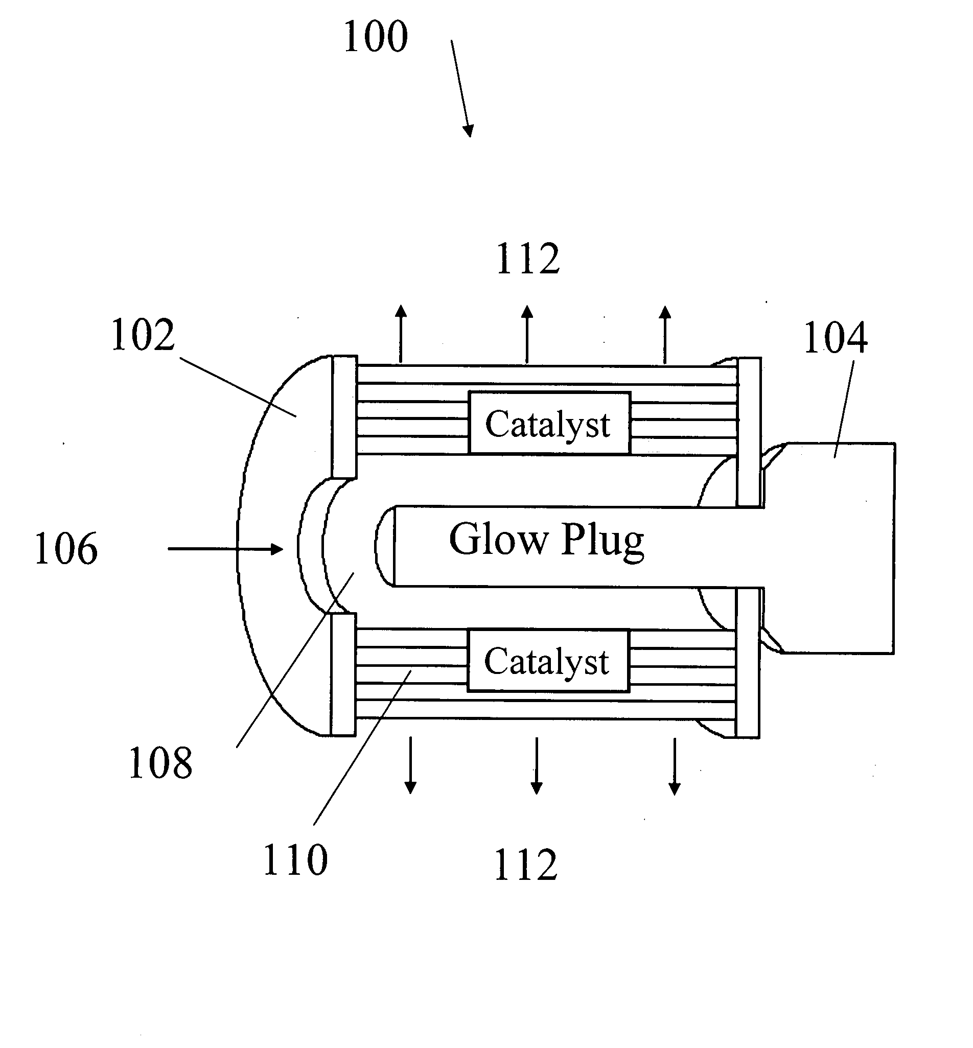
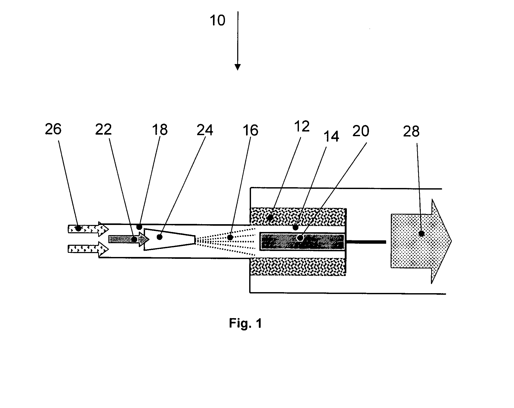
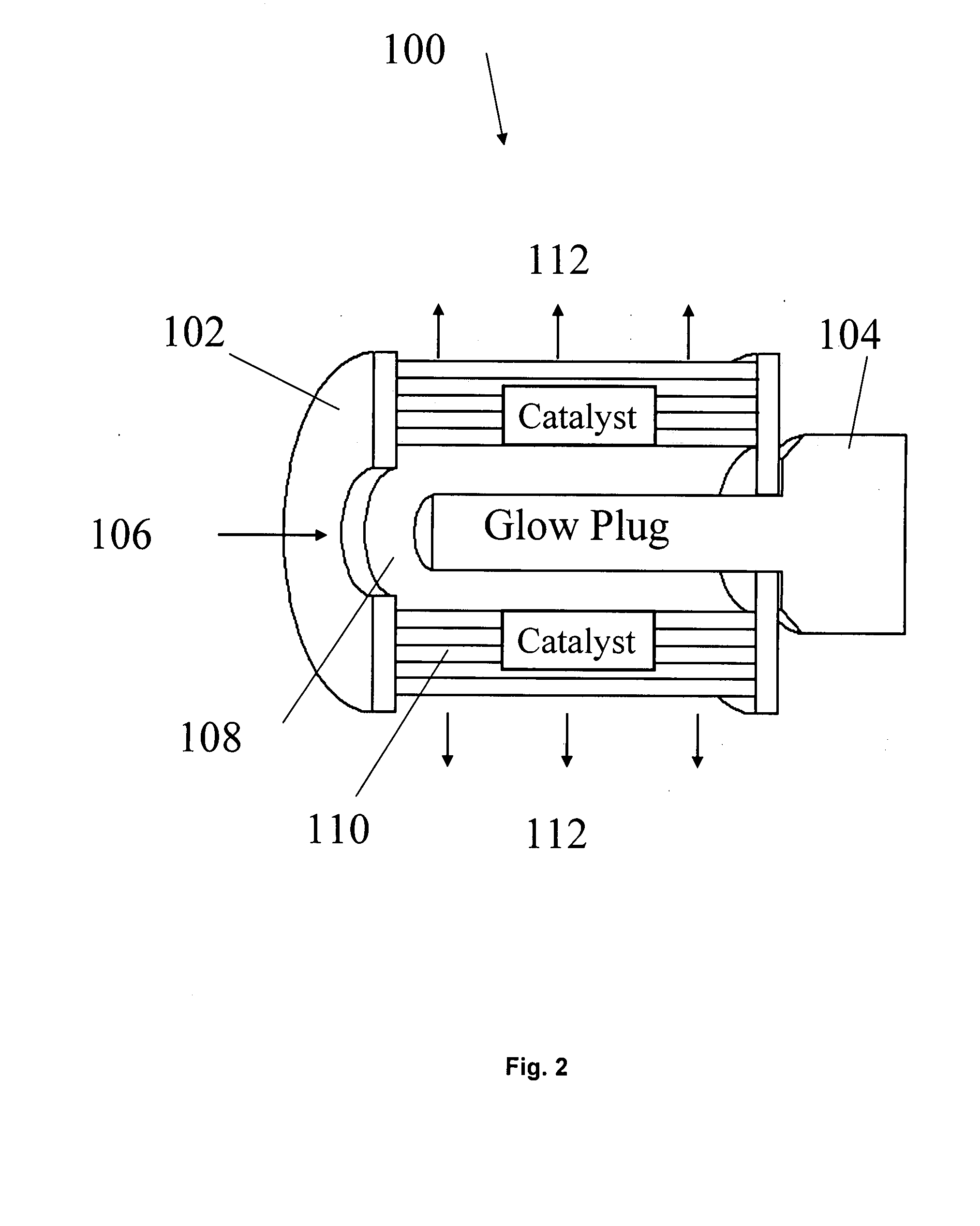
[0016]It has now been found that vaporization of the inlet fuel can be accomplished by passage through the central inlet tunnel of an operating outward flow, radial flow, exothermic catalytic reactor. A preferred system according to the present invention comprises a cooled fuel injector, a short-contact-time, ultra-short-channel-length substrate catalytic reactor, and an ignition device (e.g. glow plug). The liquid fuel and air (atomizer air and secondary air) are injected into the tubular center axial flow hot box for vaporization of the fuel droplets before the droplets strike the catalyst bed. Another embodiment of the present invention comprises the use of a coiled, radial flow, short-contact-time, ultra-short-channel-length substrate catalytic reactor. The advantages of such a configuration are disclosed in U.S. patent application Ser. No. 10 / 324,464 filed Dec. 19, 2002, the contents of which are incorporated herein by reference, particularly the teachings at Paragraphs 0014-00...


PUM

PropertyMeasurementUnit
temperatureaaaaaaaaaa
channel lengthaaaaaaaaaa

Abstract

A method and a system for the vaporization of a liquid fuel is provided and includes providing a supply of a liquid fuel and an oxidant, atomizing the liquid fuel and mixing it with the oxidant, vaporizing the fuel in thermal radiation, catalytically reacting the fuel oxidant mixture, and providing an ignition source for initiating the catalytic reaction. A hydrocarbon fuel can be mixed with oxygen, as a constituent of air, preferably forming a fuel rich fuel air mixture that passes through a catalytic reactor having an ultra-short channel length metal monolith substrate. The fuel air mixture is vaporized and partially oxidized.

Description

CROSS-REFERENCE TO RELATED APPLICATION[0001]This application is a continuation in part of U.S. patent application Ser. No. 10 / 902,512; which in turn claimed the benefit of U.S. Provisional Application No. 60 / 491,604 filed Jul. 31, 2003.BACKGROUND OF THE INVENTION[0002]1. Field of the Invention[0003]The present invention is directed to a method and system for the process of reactively converting a liquid fuel into a gasified stream. The method and system of the present invention also provide a means for quickly starting and operating the process at a variety of inlet conditions including ambient inlet conditions. More particularly, the method and system include the steps of atomizing a liquid fuel, mixing the atomized fuel with an oxidizer in fuel rich proportions, partially vaporizing the fuel and passing the resulting stream through a catalyst bed. The catalyst bed can be suitable for supporting partial oxidation / reforming reactions at high space velocity and can be integrated with...

Claims


Application Information

Patent Timeline
Patent Type & Authority Applications(United States)
IPC IPC(8): C10K3/02B01J8/02B01J19/26C01B3/36C01B3/38C10G11/02
CPCB01J4/002C10G11/02B01J8/0221B01J8/0278B01J8/0285B01J19/26B01J2208/00716C01B3/36C01B3/363C01B3/382C01B2203/0244C01B2203/0255C01B2203/0844C01B2203/1247C01B2203/142C01B2203/82B01J8/0214C01B3/386C01B2203/0261B01J8/02
Inventor ROYCHOUDHURY, SUBIRLYUBOVSKY, MAXIMBERRY, JONATHAN
Owner PRECISION COMBUSTION
Why Eureka
Try Eureka