Gun support

a technology for supporting and guns, applied in the field of accessory equipment for guns, can solve the problems of unduly complex and costly conventional supports, and achieve the effect of convenient installation and removal of supports, and convenient use and installation

Inactive Publication Date: 2007-04-03
BENSON GARY A
View PDF33 Cites 34 Cited by
  • Summary
  • Abstract
  • Description
  • Claims
  • Application Information

AI Technical Summary

Benefits of technology

[0003]The present invention provides a simple, one-piece support that is easy to use and install, will not interfere with the shooter's aiming or firing of the gun, and is rugged and long-lived. It can be installed on the gun without using any tools, and requires no modification of the gun itself. It causes no damage or injury of any kind to the gun when installed thereon. The support is particularly suited for use by waterfowl hunters who employ the technique of lying on their back in a field while covered with camouflage material, awaiting the arrival of game birds. Such hunters need a way of supporting the muzzle end of the gun barrel up and out of mud, debris and moisture while they rest the gun alongside themselves on the ground. It is also well suited for other types of still hunting, such as turkey and dove hunting, and can be used to support the gun for display purposes, such as on a mantel or shelf.
[0004]In one preferred embodiment, the support comprises a one-piece, integrally molded body having a generally horizontally extending, tubular hub that can be slipped onto and off of the muzzle end of the barrel. A pair of support legs diverge downwardly and outwardly from opposite sides of the hub and terminate in lowermost, ground-engaging tips that are adapted to keep the barrel up off the ground. Preferably, the support is constructed from a synthetic resinous material and has a slot along the top of the hub that permits opposed halves of the hub to be slightly resiliently opened and closed to facilitate installation and removal of the support from the gun barrel. The legs may be advantageously grasped and squeezed by the user to effect such resilient flexing of the hub.

Problems solved by technology

However, conventional supports are unduly complex, costly, and made from a multitude of parts that can malfunction or become disassembled and lost.

Method used


Image

  • Gun support
  • Gun support
  • Gun support

Examples


Embodiment Construction

[0012]The present invention is susceptible of embodiment in many different forms. While the drawings illustrate and the specification describes certain preferred embodiments of the invention, it is to be understood that such disclosure is by way of example only. There is no intent to limit the principles of the present invention to the particular disclosed embodiments.

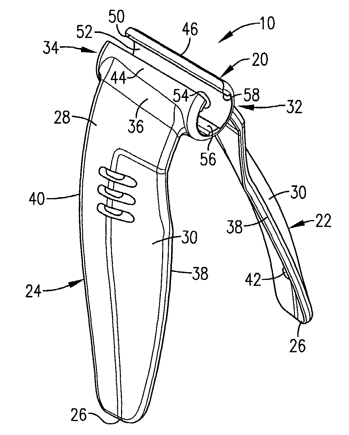
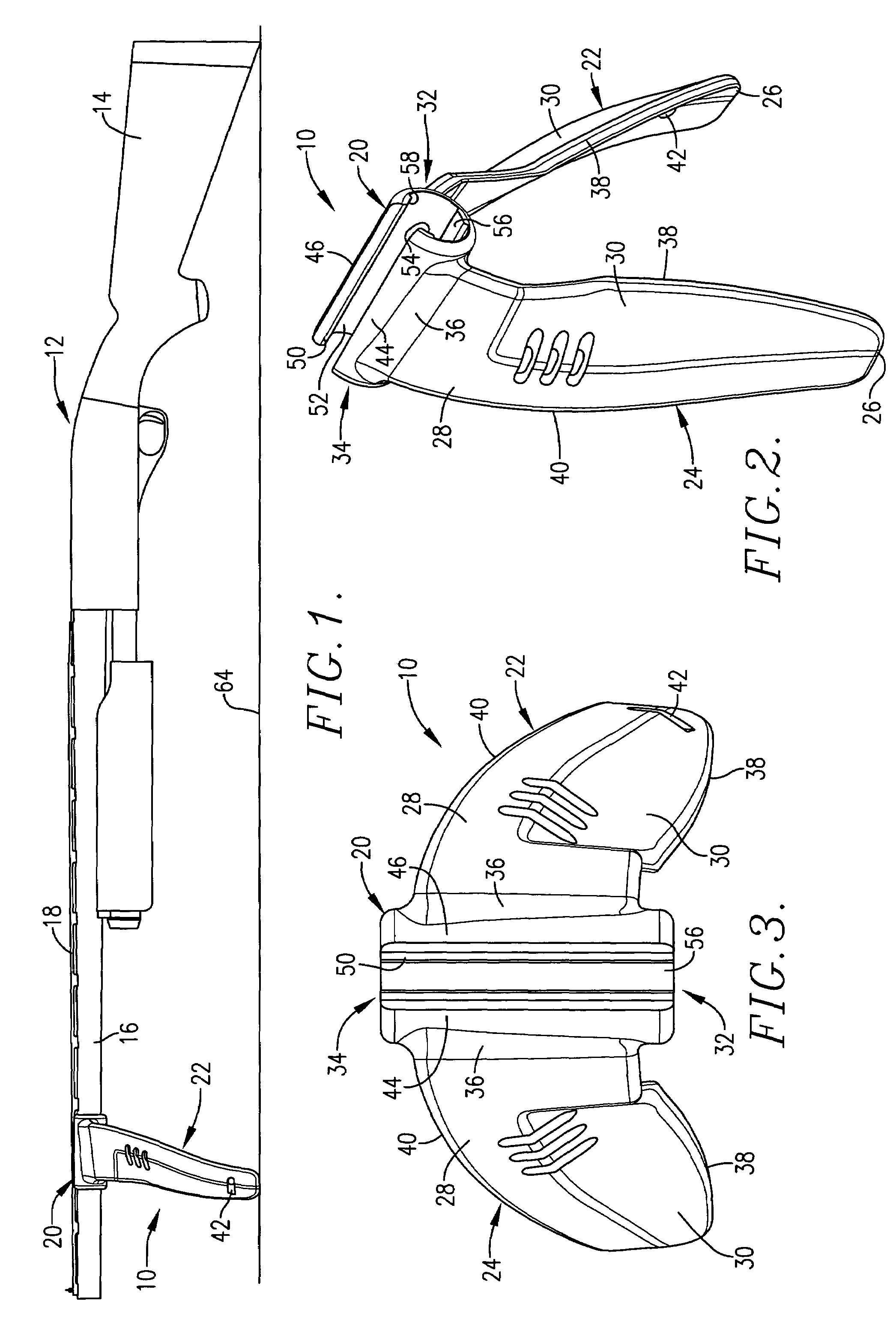
[0013]The support 10 as illustrated in FIG. 1 is adapted to be installed on a gun 12, particularly a shotgun, having a stock 14 and a barrel 16 among other components. A vent or rib 18 extends along the top of barrel 16 and is of generally rectangular cross-sectional configuration as illustrated in FIGS. 6 and 7.

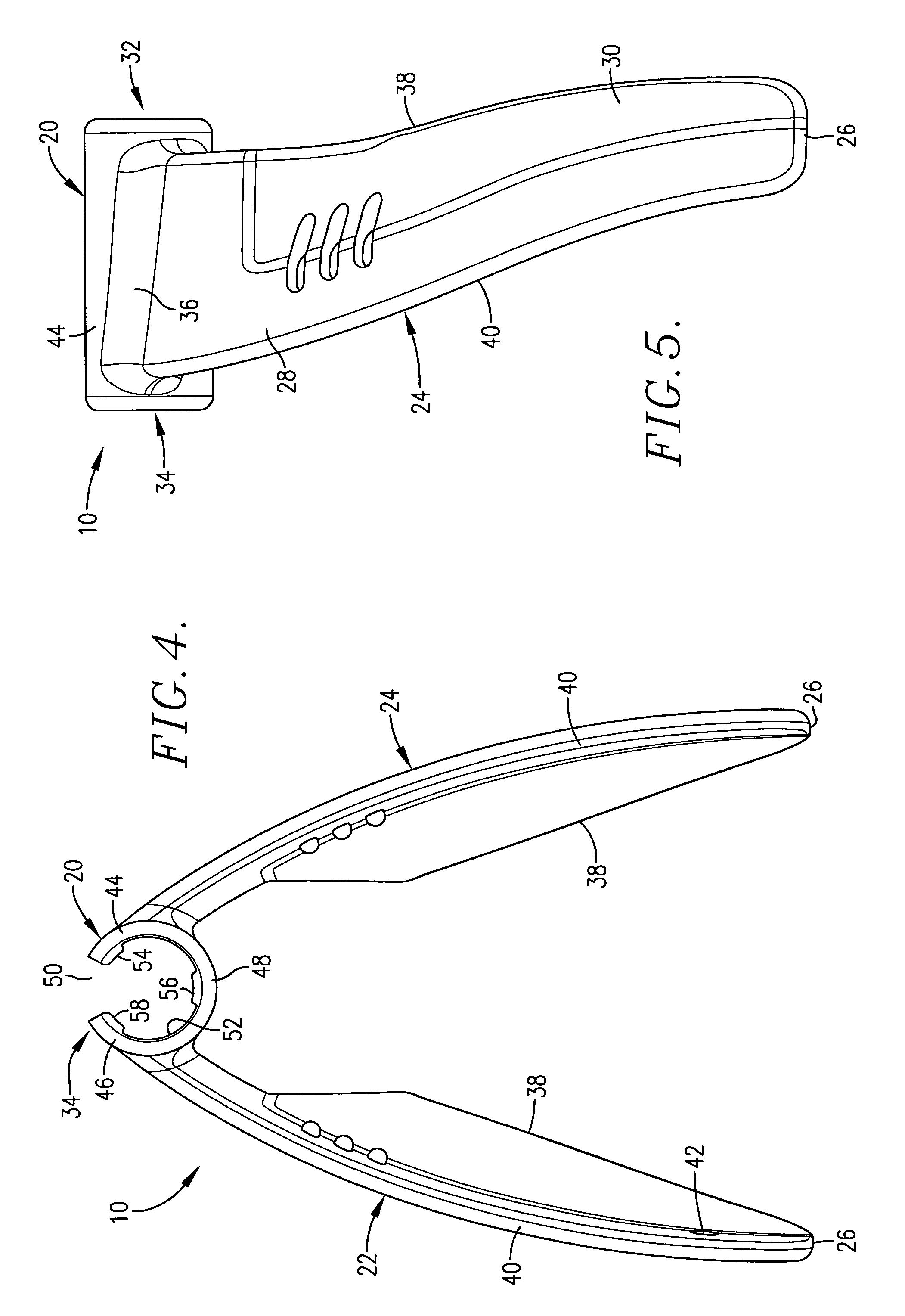
[0014]Support 10 comprises a one-piece unitary body, preferably molded from a synthetic resinous material, having a normally horizontally extending, generally tubular, barrel-receiving hub 20 and a pair of supporting legs 22 and 24 integrally joined with hub 20. Legs 22 and 24 diverge outwardly away from one an...


PUM


Abstract

A bipod type gun support has a generally cylindrical hub that defines a barrel-receiving bore that can be slipped onto and off of the muzzle end of the gun. Downwardly diverging legs are integrally joined to opposite sides of the hub to present a one-piece construction. A slot along the top of the hub facilitates a slight amount of resilient flexing of sidewall portions of the hub toward and away from one another when the diverging legs are squeezed and released, thus enlarging the bore of the hub sufficiently to facilitate installation and removal of the support from the barrel. Preferably, the support is molded from a synthetic resinous material.

Description

TECHNICAL FIELD[0001]The present invention relates to the field of accessory equipment for guns, particularly shotguns, and relates more specifically to a bipod type support attachable to the barrel of the gun to support the barrel when the gun is placed on the ground or other surface.BACKGROUND AND SUMMARY[0002]Various types of bipod supports for shotguns and rifles are known in the art. However, conventional supports are unduly complex, costly, and made from a multitude of parts that can malfunction or become disassembled and lost.[0003]The present invention provides a simple, one-piece support that is easy to use and install, will not interfere with the shooter's aiming or firing of the gun, and is rugged and long-lived. It can be installed on the gun without using any tools, and requires no modification of the gun itself. It causes no damage or injury of any kind to the gun when installed thereon. The support is particularly suited for use by waterfowl hunters who employ the tec...

Claims


Application Information

Patent Timeline
Patent Type & Authority Patents(United States)
IPC IPC(8): F41A23/08
CPCF41A23/08
Inventor BENSON, GARY A.
Owner BENSON GARY A
Why Eureka
Try Eureka