Paving system for floor tiles

a paving system and floor tile technology, applied in the direction of structural elements, building components, decorative arts, etc., can solve the problems of individual tile cracks and floor covering cracks, and achieve the effect of avoiding mistakes during paving, and reducing the cost of paving

Active Publication Date: 2007-04-03
CLICKN WALK +1
View PDF42 Cites 108 Cited by
  • Summary
  • Abstract
  • Description
  • Claims
  • Application Information

AI Technical Summary

Benefits of technology

The patent text describes a method for paving with high-quality tiles, such as granite flagstones, that offers several advantages. Firstly, the cost of the paving system is less significant compared to other materials, and secondly, it reduces the likelihood of mistakes during paving, even if the paving personnel are not well trained. Additionally, the paving costs are significantly lower. The text also mentions that the method allows for quick and cost-effective paving of granite floors on existing wooden constructions without requiring much preparatory work. Furthermore, it explains that the method can be used to pave the floors of prefabricated timber houses with granite and natural stone.

Problems solved by technology

The technical problem addressed in this patent is the difficulty and time-consuming process of paving floors using traditional methods, which require special tools, materials, and skill. Additionally, the resulting seams cannot be easily removed without damaging the tiles. The invention aims to provide a paving system that can be easily carried out by unskilled personnel and allows for easy removal of the paving without causing damage to the tiles.

Method used


Image

  • Paving system for floor tiles
  • Paving system for floor tiles
  • Paving system for floor tiles

Examples


working examples

[0039]

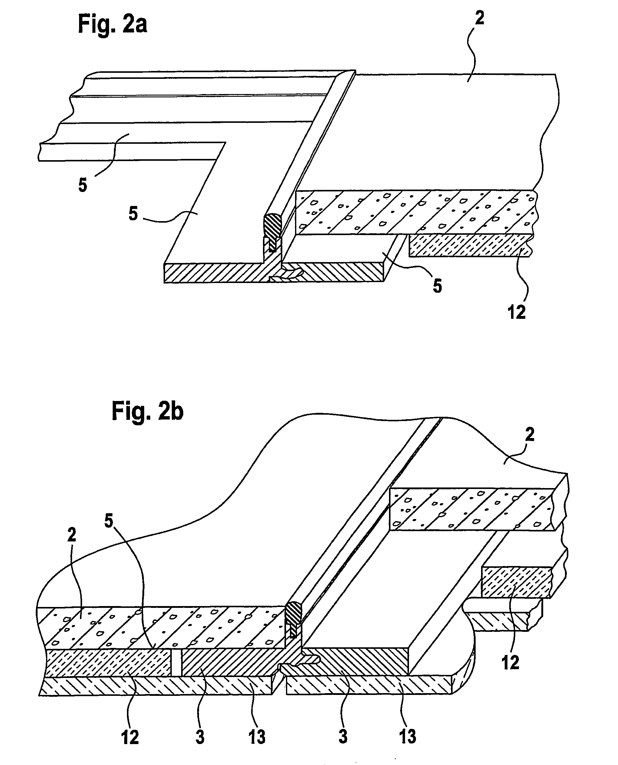
[0040]The working examples illustrated involve floor coverings comprising a number of flagstones, eg, granite flagstones, that abut each other in rows laid out on a substrate, eg, a smooth coating or boarded flooring, so as to float on intermediate spacing material.

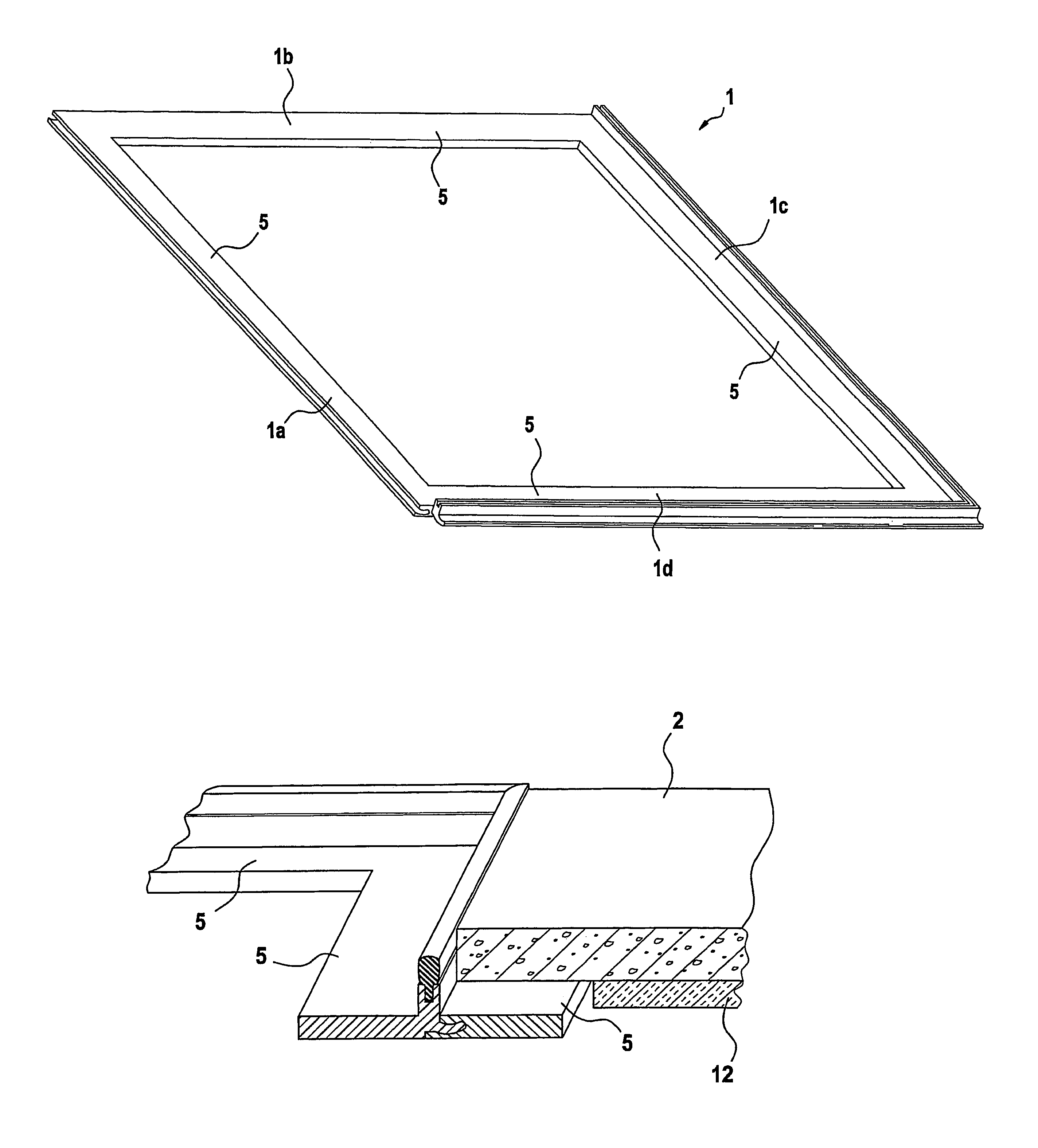
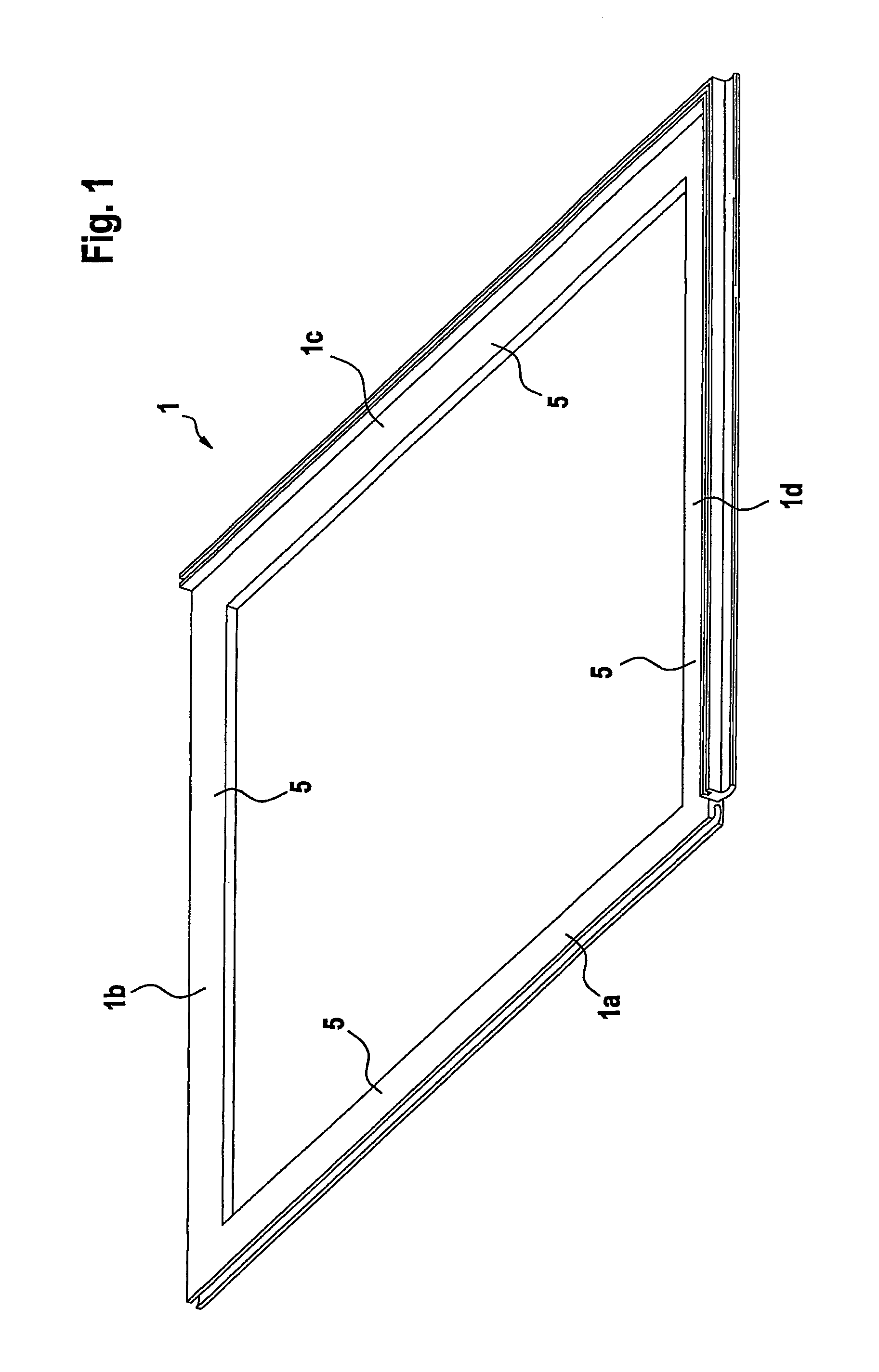
[0041]FIG. 1 is a perspective view of a square frame 1 to accommodate a tile (not shown in this figure), eg, a granite flagstone. Frame 1 is of a plastics material and is pre-formed; it may consist of an undivided injection molding or, alternatively, of individual elements made from extruded profiled material. The material used may be recycled plastics material.

[0042]Of the four limbs 1a to 1d of frame 1, two adjacent limbs 1c, 1d have a plug-type profile 3 which is shown in FIG. 4 in cross-section. The other two limbs 1a, 1b have a socket-type profile 4 as shown in FIG. 5 in cross-section. All four limbs 1a to 1d have a paving strip 5, on which the tile 2 to be placed in the frame rests in the paved state.

[0043]FIG...


PUM

PropertyMeasurementUnit
Timeaaaaaaaaaa
Widthaaaaaaaaaa
Areaaaaaaaaaaa

Abstract

The invention relates to a paving system for tiles, especially flagstones, for paving ceilings, walls, or floors, in which each tile is provided with a paving frame on which the tile rests over at least part of its area. The paving frames comprise, on each of two adjacent (intersecting) limbs, a fin for the accommodation of a rubber-elastic sealing profile that defines the width of the seam.

Description


Claims


Application Information

Patent Timeline
Owner CLICKN WALK
Why Eureka
Try Eureka