Automatic installation equipment and installation method of geothermal floor

An automatic installation and geothermal floor technology, which is applied in the direction of construction and building construction, can solve the problems of high paving cost, low work efficiency, poor paving accuracy, etc., and achieve the effect of high paving accuracy and reducing paving cost

Pending Publication Date: 2021-12-31
ZHEJIANG LINGGE WOOD
View PDF1 Cites 0 Cited by
  • Summary
  • Abstract
  • Description
  • Claims
  • Application Information

AI Technical Summary

Problems solved by technology

[0005] A technical purpose of the present invention is to overcome the problems of low manual paving work efficiency, high paving cost and poor paving accuracy existing in the prior art, thereby providing a geothermal floor paving equipment that can be automatically installed; The second technical purpose of the present invention is to provide a paving method for this kind of automatic installation equipment

Method used


Image

  • Automatic installation equipment and installation method of geothermal floor
  • Automatic installation equipment and installation method of geothermal floor
  • Automatic installation equipment and installation method of geothermal floor

Examples


Embodiment

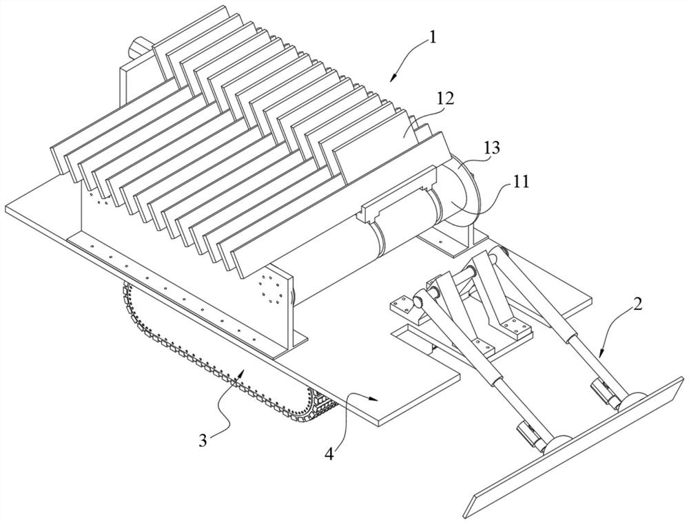
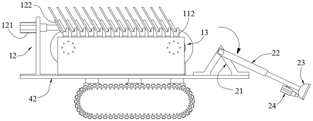
[0040] Example: Reference figure 1 The automatic installation equipment for self-adhesive flooring shown includes a feeding device 1, a paving device 2, a feeding device 3 that moves the feeding device 1 and the paving device 2 horizontally and vertically, and a control system. The feeding device 1 The paving device 2 is fixed on the feeding device 3 through the mounting seat 4, and the axes of the feeding device 1 and the paving device 2 coincide.

[0041] Mount 4

[0042]The mounting base 4 includes a base 41 fixedly connected to the feeding device 3 , a turntable 42 disposed on the base 41 , and a driving structure 43 for driving the turntable 42 to rotate relative to the base 41 . Wherein the driving structure 43 can be any structure in the prior art, for example, the base 41 is a hollow structure, the driving structure 43 is fixedly installed in the rotating motor in the base 41, and its extended end is fixedly connected with the turntable 42; or, Through gear transmiss...


PUM


Abstract

The embodiment of the invention discloses automatic installation equipment and an installation method of a self-bonding floor. The automatic installation equipment comprises a feeding device, a paving device, a feeding device and a control system, wherein the feeding device is used for enabling the feeding device and the paving device to move transversely and longitudinally, and the feeding device and the paving device are fixedly arranged on the feeding device through a mounting base; the mounting base comprises a base body fixedly connected with the feeding device, a rotary table arranged on the base body and a driving structure for driving the rotary table to rotate relative to the base body; the feeding device comprises a discharging table fixedly installed on the rotary table and a pushing structure used for intermittently moving floor blocks on the discharging table towards one side of the paving device, and a feeding position is formed at the tail end of the discharging table; and the paving device comprises a base fixedly installed on the rotary table, a paving arm rotatably arranged on the base, a vacuum suction cup arranged at the end of the paving arm and a motor for driving the paving arm to rotate, and the paving arm carries the vacuum suction cup to swing in a reciprocating mode between the feeding position and a discharging position.

Description

technical field [0001] The application relates to the technical field of floor paving, in particular to an automatic installation device suitable for geothermal floors, and the application also relates to an installation method of the automatic installation device. Background technique [0002] For the sake of heating effect, the laying method of geothermal floor is mostly straight laying method, that is, the floor boards are directly laid on the ground cushion without passing through the keel. The connection methods between adjacent geothermal floor plates are mostly in the form of flat buckle-and-groove, lock-and-groove or other metal fasteners. However, the splicing of grooves and the use of metal fasteners will greatly reduce the efficiency of paving, and a lot of labor is required. [0003] For this reason, a self-adhesive pavement form has been proposed in the prior art, that is, the floor boards can be bonded to the floor mat. Specifically, the ground cushion materi...

Claims


Application Information

Patent Timeline
Patent Type & Authority Applications(China)
IPC IPC(8): E04F21/22
CPCE04F21/22
Inventor 姚金国李明飞方英英
Owner ZHEJIANG LINGGE WOOD
Why Eureka
Try Eureka