
Single phase fluid sampler systems and associated methods

a single-phase fluid and sampler technology, applied in the field of single-phase fluid sampler systems and methods, can solve the problems of increased cost, preparation time and safety hazards associated, and achieve the effects of increasing pressure, increasing pressure in the pressure source, and increasing pressur

Inactive Publication Date: 2007-04-03
HALLIBURTON ENERGY SERVICES INC
View PDF17 Cites 93 Cited by
  • Summary
  • Abstract
  • Description
  • Claims
  • Application Information

AI Technical Summary

Benefits of technology

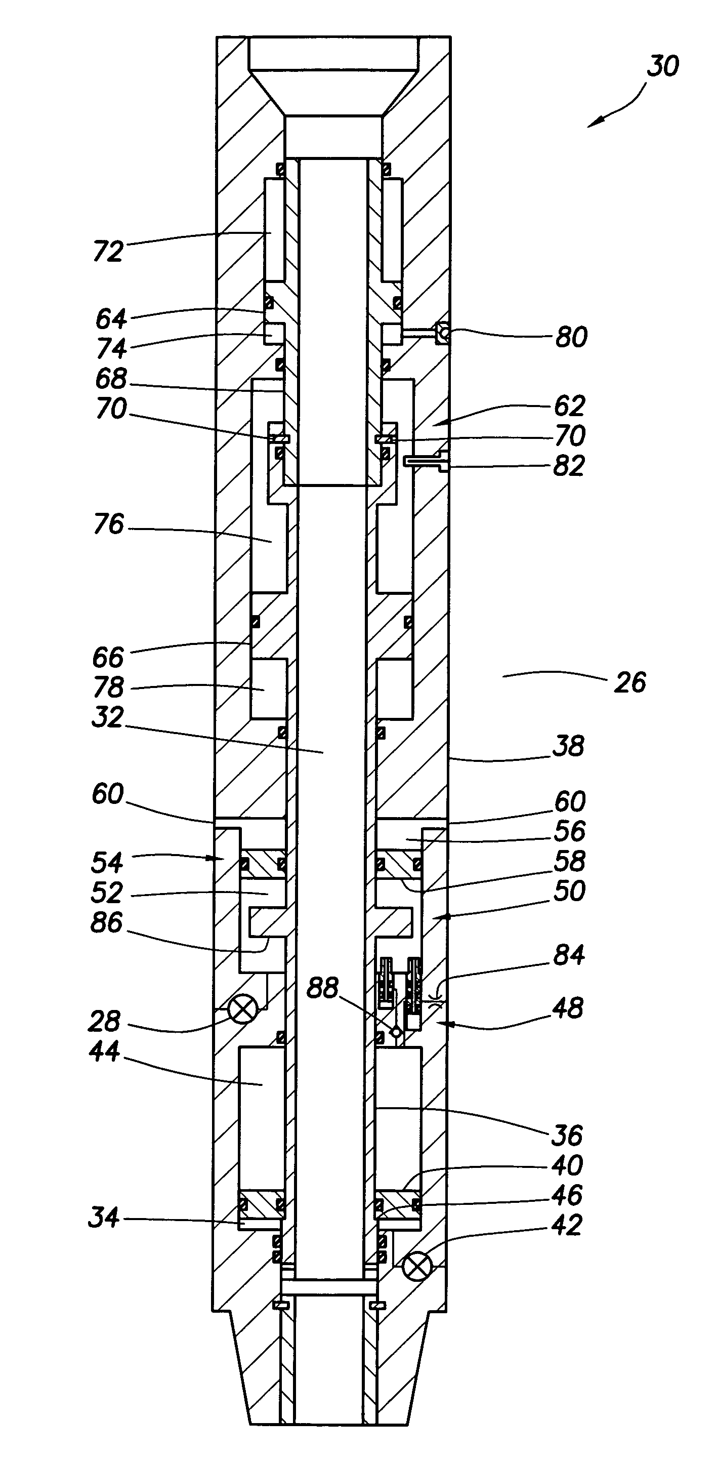
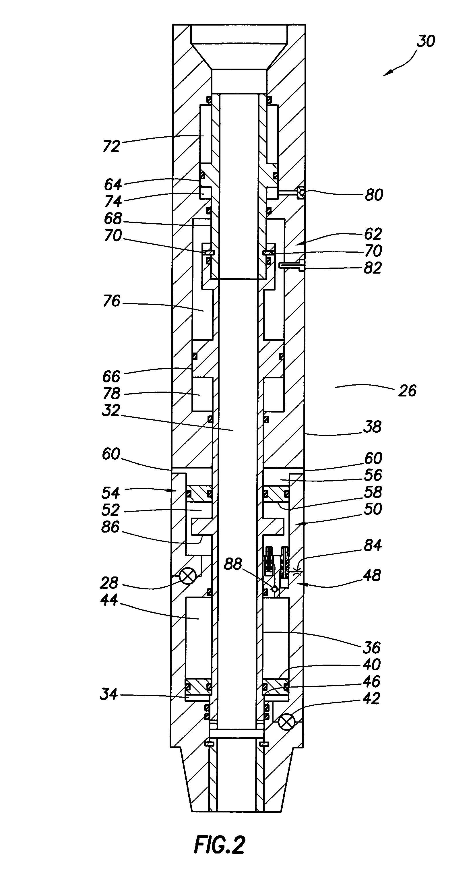
[0006]In one aspect of the invention, a fluid sampling method for taking at least one fluid sample is provided. The method includes the steps of: receiving the fluid sample into a sample chamber of a fluid sampler; pressurizing the fluid sample in the sample chamber using a pressure source of the fluid sampler; and increasing pressure in the pressure source while the pressure source is in the well, thereby applying increased pressure to the fluid sample in the sample chamber.
[0007]In another aspect of the invention, a fluid sampler system for use in taking at least one fluid sample is provided. The system includes a fluid sampler with a sample chamber, a pressure source for pressurizing the sample chamber, and a device which operates to increase pressure in the pressure source while the fluid sampler is in the well.
[0008]In yet another aspect of the invention, a method of taking a fluid sample in a well includes the st

Problems solved by technology

Unfortunately, this requires that the highly pressurized nitrogen chamber be handled at the surface.
Another problem with this technique is that, if multiple fluid samples are to be taken, then multiple nitrogen chambers need to be provided, pressurized and maintained.
This substantially increases the cost, preparation time and safety hazards associated with the sampling operation.

Method used


Image

  • Single phase fluid sampler systems and associated methods
  • Single phase fluid sampler systems and associated methods
  • Single phase fluid sampler systems and associated methods

Examples


Embodiment Construction

[0022]It is to be understood that the various embodiments of the present invention described herein may be utilized in various orientations, such as inclined, inverted, horizontal, vertical, etc., and in various configurations, without departing from the principles of the present invention. The embodiments are described merely as examples of useful applications of the principles of the invention, which is not limited to any specific details of these embodiments.

[0023]In the following description of the representative embodiments of the invention, directional terms, such as “above”, “below”, “upper”, “lower”, etc., are used for convenience in referring to the accompanying drawings. In general, “above”, “upper”, “upward” and similar terms refer to a direction toward the earth's surface along a wellbore, and “below”, “lower”, “downward” and similar terms refer to a direction away from the earth's surface along the wellbore.

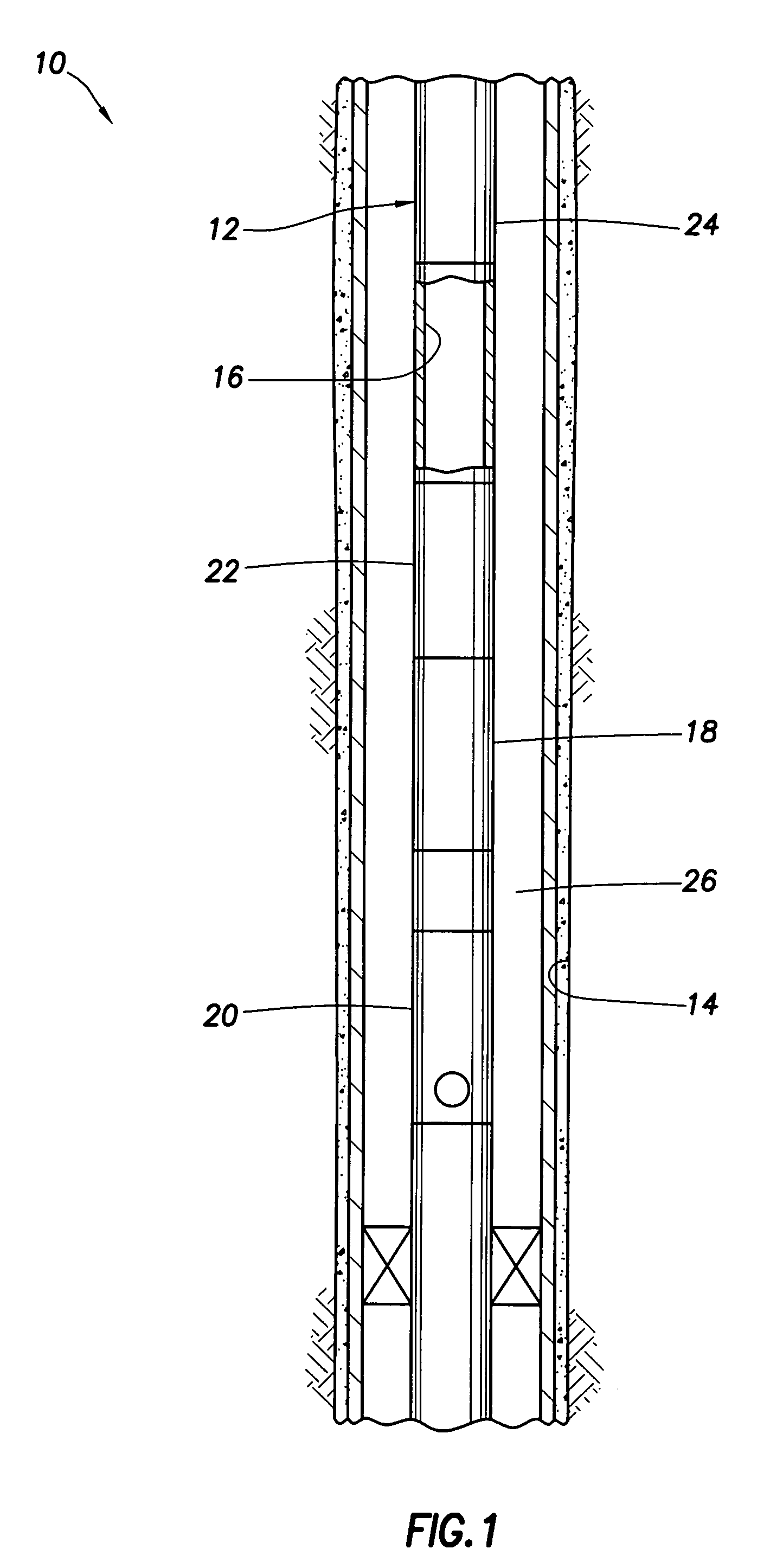
[0024]Representatively illustrated in FIG. 1 is a fluid sampler...


PUM


Abstract

A single phase fluid sampler system and associated methods. A fluid sampling method includes the steps of: receiving a fluid sample into a sample chamber of a fluid sampler; pressurizing the fluid sample using a pressure source; and increasing pressure in the pressure source while the pressure source is in the well, thereby applying increased pressure to the fluid sample in the sample chamber. Another method includes the step of applying pressure to the well to thereby increase pressure in the pressure source, and to thereby increase pressure on the fluid sample. A fluid sampler system includes a fluid sampler with a sample chamber, a pressure source for pressurizing the sample chamber, and a device which operates to increase pressure in the pressure source while the fluid sampler is in the well.

Description

BACKGROUND[0001]The present invention relates generally to equipment utilized and operations performed in conjunction with a subterranean well and, in an embodiment described herein, more particularly provides single phase fluid sampler systems and methods.[0002]The benefits of retrieving a formation fluid sample without permitting the fluid sample to reach its bubble point are well known. One technique typically used to retrieve a single phase fluid sample is to transport a highly pressurized nitrogen chamber downhole, flow the fluid sample into a sample chamber, and then apply pressure from the nitrogen chamber to the fluid sample. Unfortunately, this requires that the highly pressurized nitrogen chamber be handled at the surface.[0003]Another problem with this technique is that, if multiple fluid samples are to be taken, then multiple nitrogen chambers need to be provided, pressurized and maintained. This substantially increases the cost, preparation time and safety hazards assoc...

Claims


Application Information

Patent Timeline
IPC IPC(8): E21B49/00
CPCE21B49/081
Inventor WRIGHT, ADAM D.LARIMORE, DAVIDSCHULTZ, ROGER L.CARLSON, TIMOTHY R.IRANI, CYRUS
Owner HALLIBURTON ENERGY SERVICES INC
Learn More