Ink ejecting head and method for making the same

a technology of ejecting head and printing head, which is applied in the field of ejecting head, can solve the problems of scratching the printing medium, increasing production costs, and feeding problems, and achieves the effect of raising production costs and sacrificing reliability

Inactive Publication Date: 2007-04-03
SONY CORP
View PDF2 Cites 2 Cited by
  • Summary
  • Abstract
  • Description
  • Claims
  • Application Information

AI Technical Summary

Benefits of technology

[0012]Accordingly, an object of the present invention is to perform bonding of a head chip in the process of producing an ink ejecting head, without forming openings for bonding on a nozzle sheet, without suffering from constraints on the distance between the head chip and the nozzle sheet, without sacrificing reliability, and without raising the production costs.

Problems solved by technology

This involves many production processes and thus an increase in production costs.
The projections may cause feeding problems (such as jamming) of a printing medium or may scratch the printing medium, since the printing medium such as paper slides over the ink ejecting surface.

Method used


Image

  • Ink ejecting head and method for making the same
  • Ink ejecting head and method for making the same
  • Ink ejecting head and method for making the same

Examples


Embodiment Construction

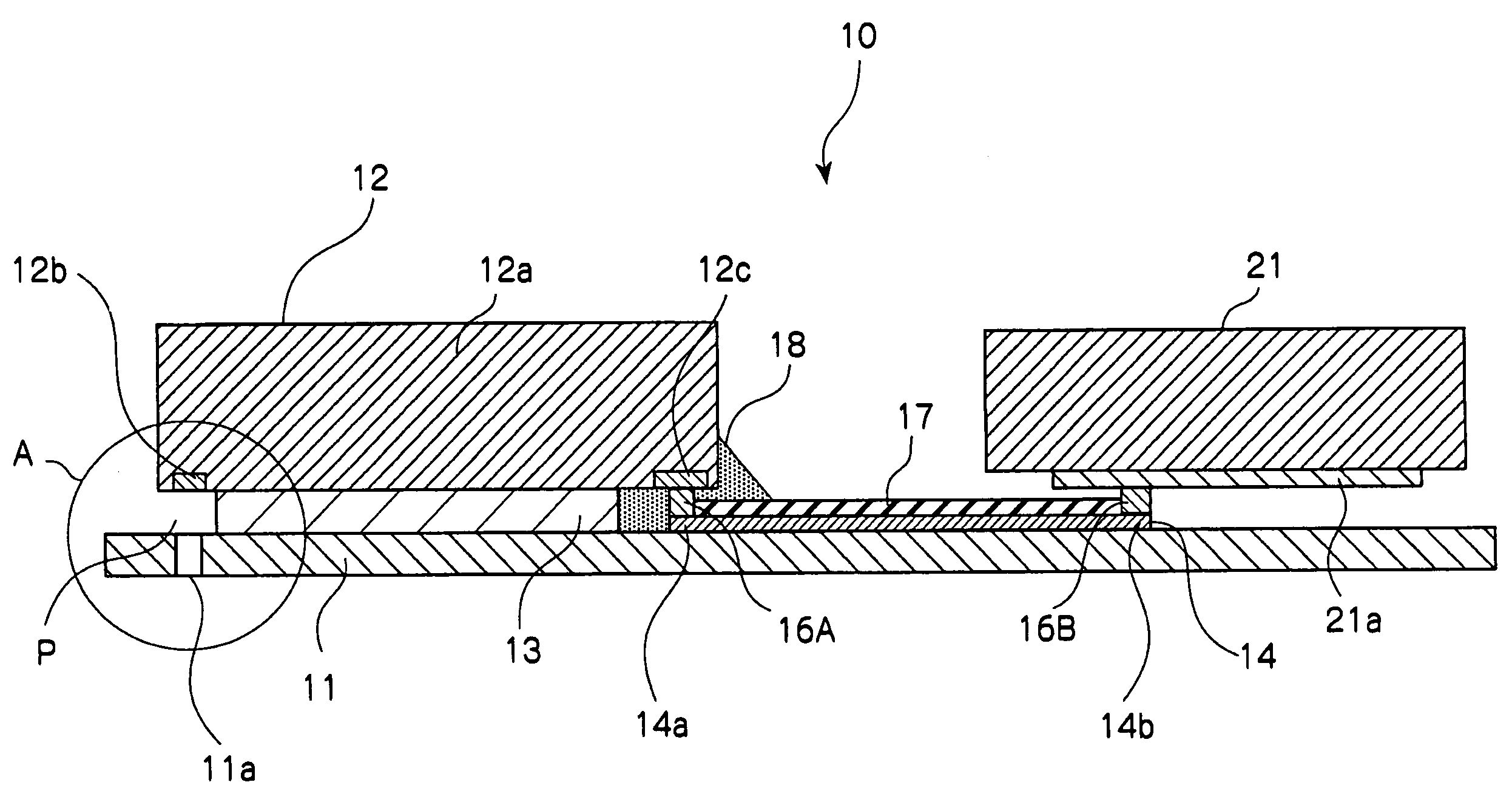
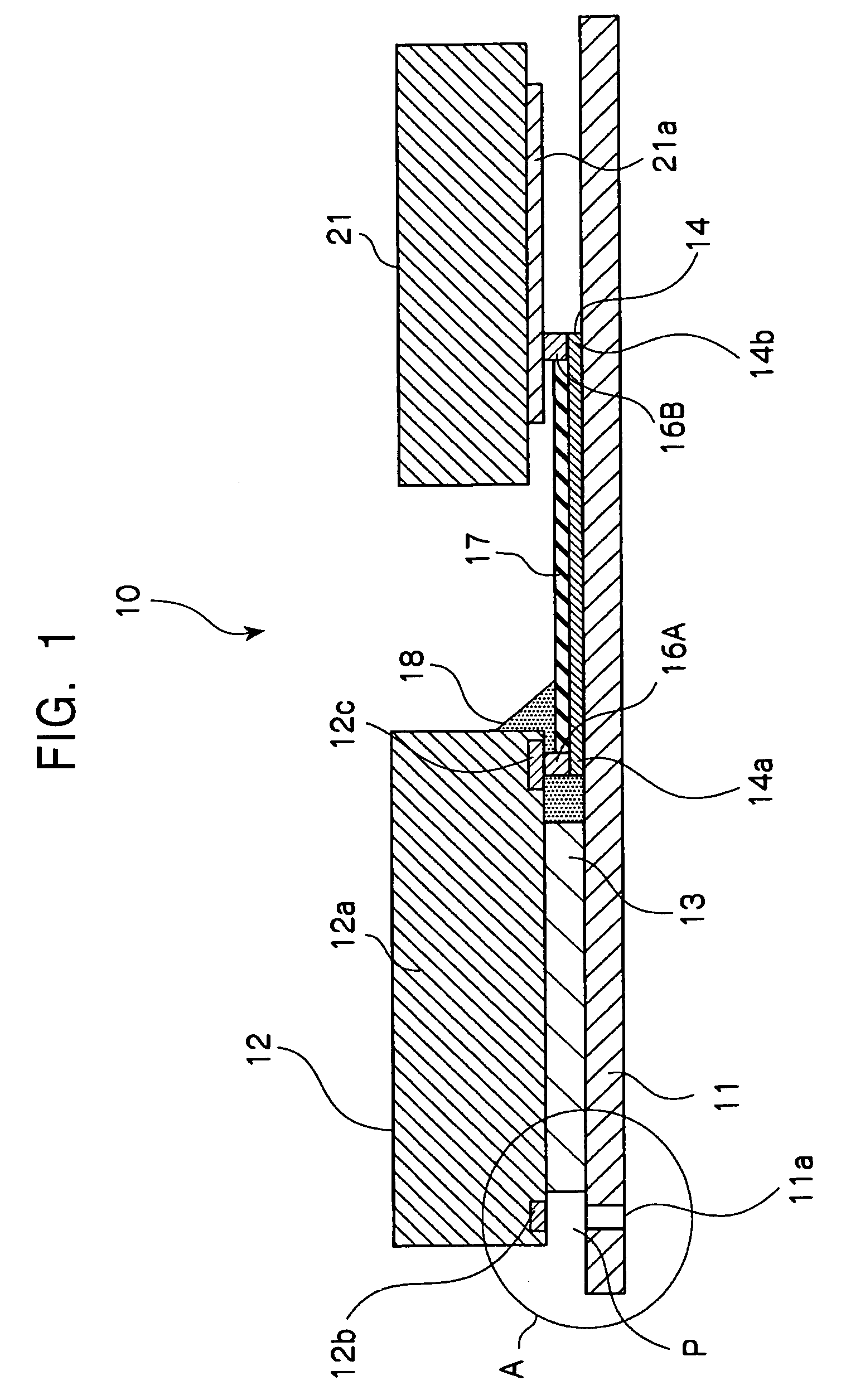
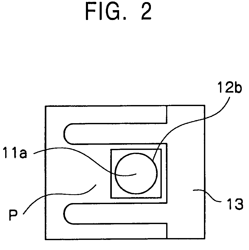
[0028]An embodiment of the present invention will now be described with reference to the drawings. FIG. 1 is a front cross-sectional view of an ink ejecting head 10 according to an embodiment of the present invention. FIG. 2 is a detailed illustration of the section A in FIG. 1 and is a bottom plan view showing a nozzle 11a, an energy generator 12b, and an ink chamber P.

[0029]Referring to FIG. 1, a nozzle sheet 11 is formed of a flexible printed circuit (FPC) where a circuit is mounted on a flexible film ranging from about 10 to 50 μm in thickness. A wiring layer 14 (conductor) formed of a pattern of copper traces is disposed on the upper (in FIG. 1) surface of the nozzle sheet 11. The wiring layer 14 connects a head chip 12 to a printed circuit board 21 that controls the head chip 12. The wiring layer 14, excluding the areas of a first terminal 14a and a second terminal 14b (in FIG. 1, both ends of the wiring layer 14), is overlaid with an insulating layer 17 made of the same mater...


PUM


Abstract

An ink ejecting head includes a nozzle sheet having nozzles for ejecting droplets; a head chip having an energy generator opposing each of the nozzles; a barrier layer interposed between the nozzle sheet and the head chip for forming the space for a liquid chamber; a pad provided in a surface of the head chip, the surface opposing the nozzle sheet; and a wiring layer disposed on a surface of the nozzle sheet, the surface adjacent to the head chip; and a bump disposed on the wiring layer, being at least in contact with the pad of the head chip, and bonded to the pad by ultrasonic bonding.

Description

RELATED APPLICATION DATA[0001]The present application claims priority to Japanese Application(s) No(s). P2003-030125 filed Feb. 6, 2003, which application(s) is / are incorporated herein by reference to the extent permitted by law.BACKGROUND OF THE INVENTION[0002]1. Field of the Invention[0003]The present invention relates to ink ejecting heads incorporated in, for example, inkjet printers, and also relates to methods for making the ink ejecting heads. In particular, the present invention relates to an ink ejecting head having no opening on a nozzle sheet for bonding to a head chip and no constraints on the height of a liquid chamber, and also relates to a method for making the ink ejecting head for appropriate bonding of the head chip without raising the production costs.[0004]2. Description of the Related Art[0005]A known ink ejecting head for inkjet printers requires an electrical connection between a head chip having an energy generator for applying energy to ink for ejecting ink ...

Claims


Application Information

Patent Timeline
Patent Type & Authority Patents(United States)
IPC IPC(8): B41J2/05B41J2/01B41J2/16
CPCB41J2/1603B41J2/1623B41J2/1643
Inventor TANIKAWA, TORU
Owner SONY CORP
Why Eureka
Try Eureka