Grenade having safety lever with integrated firing pin retaining clip

a safety lever and grenade technology, applied in the field of grenades and cartridges, can solve the problems of dangerous projectiles, increased pressure, and increased risk of injury, and achieve the effects of reducing the risk of injury, and sacrificing the reliability or functionality of grenades

Inactive Publication Date: 2014-05-20
COMBINED SYST
View PDF46 Cites 4 Cited by
  • Summary
  • Abstract
  • Description
  • Claims
  • Application Information

AI Technical Summary

Benefits of technology

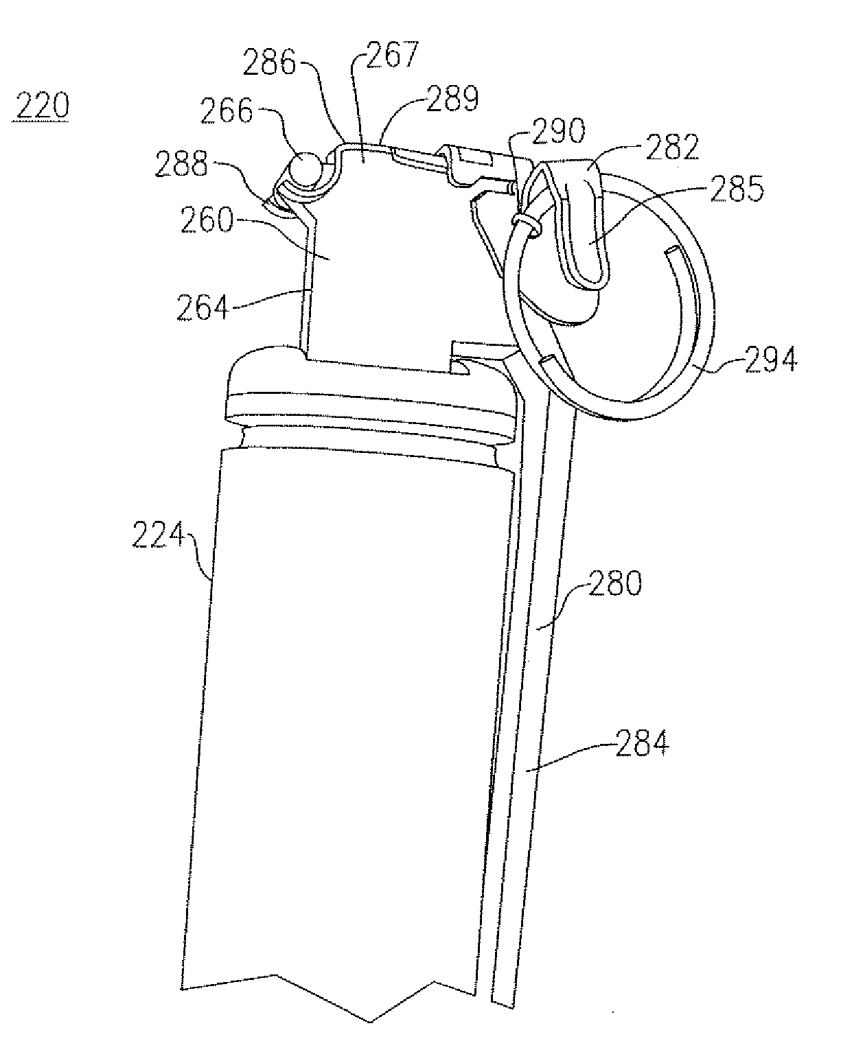
[0008]One advantage provided is greater ease in the manufacture of grenades by assimilating the above-noted safety functions within a single component, but without sacrificing reliability or functionality of the grenade. That is, the herein described safety lever includes a retaining clip that permits an arming pin of the grenade to lock the safety lever in a first or non-firing position wherein the lever continues to operate upon release of the arming pin to be caused to move between the first position and an arming position in which the fuze assembly of the grenade can be engaged. By maintaining the retaining clip within the safety lever itself and not providing a separate component, the retaining clip is maintained and released immediately after engagement with the fuze assembly based on a hinged connectivity of the safety lever with the grenade body. As a result, there is no chance of the retaining clip becoming a dangerous projectile when the grenade detonates, a clear preference, especially in non-lethal versions or otherwise creating built-up pressure in the grenade prior to detonation.
[0009]Moreover, integration of the retaining clip within the safety lever improves and simplifies manufacture and assembly of grenades incorporating same, but without sacrificing reliability.

Problems solved by technology

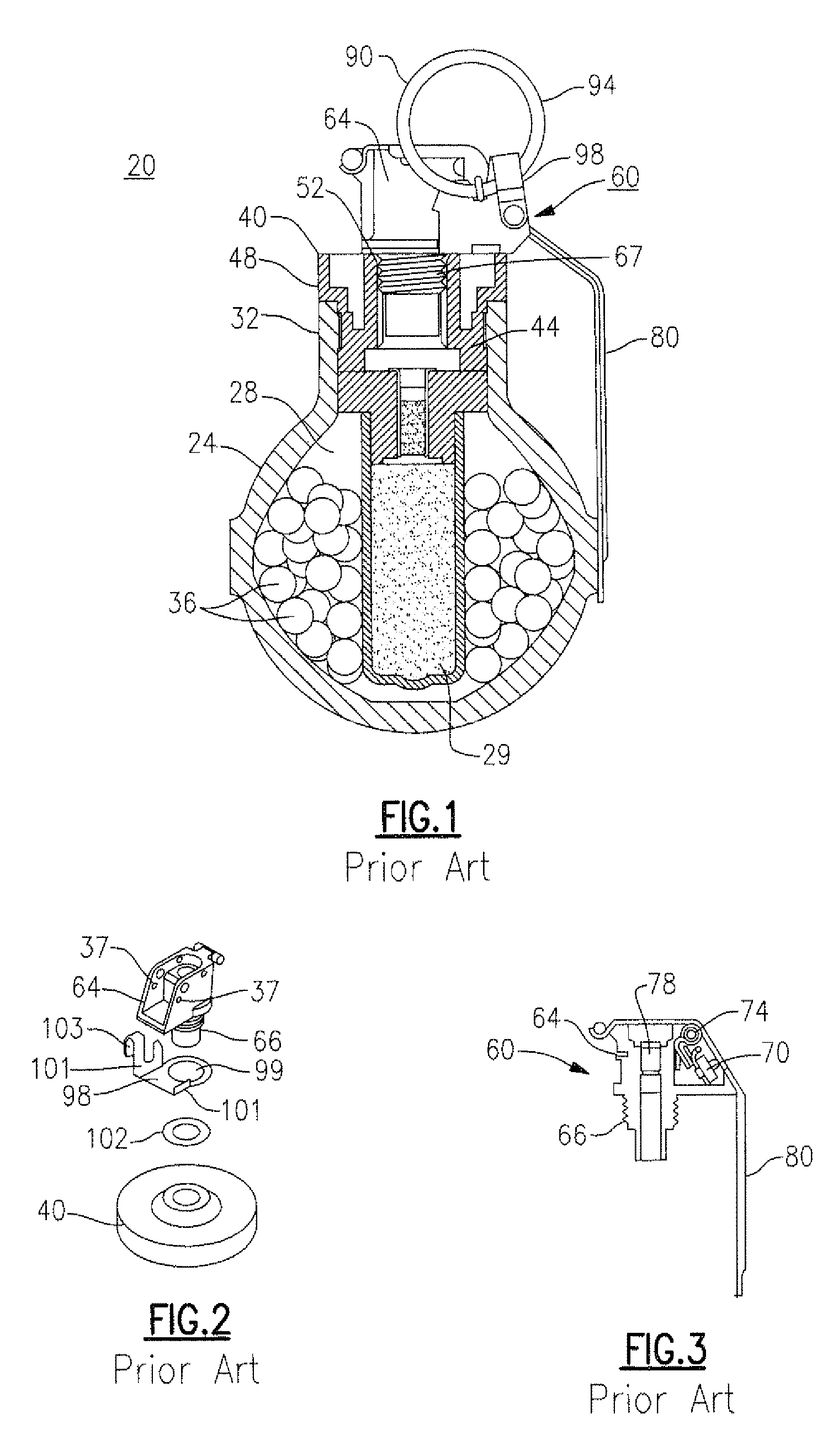
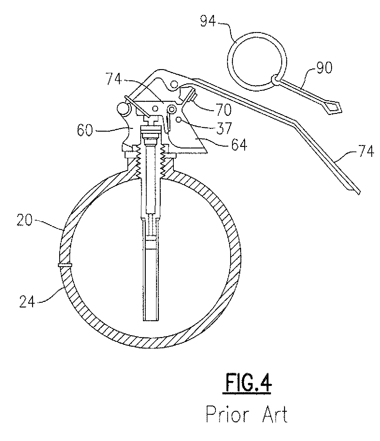
As such and particularly in the instances of non-lethal grenades, the safety lever would remain with the grenade fuze upon detonation, which could lead to a build-up of pressure as a result of the retaining clip blocking the top venting ports of the grenade.
First, it could break the fuze body which would cause the actual fuze body to separate and be thrown clear from the grenade upon detonation, becoming a dangerous projectile and creating potential for injury.
Second and as pressure is blocked at the top of the grenade, it could build-up additional pressure at the bottom ports of the grenade, thereby permitting the grenade to move on the floor.

Method used


Image

  • Grenade having safety lever with integrated firing pin retaining clip
  • Grenade having safety lever with integrated firing pin retaining clip
  • Grenade having safety lever with integrated firing pin retaining clip

Examples


Embodiment Construction

[0023]The following embodiments described herein relate to a grenade having a safety feature that is integrated directly within the handle or lever of the grenade. Throughout the course of discussion, various terms are used to aid in providing a suitable frame of reference with regard to the accompanying drawings. To that end, terms such as “above”, “below”, “top”, “bottom”, “upward”, downward”, “proximal”, “distal” and the like are used throughout. These terms, however, are not intended to be overlimiting of the present invention as claimed. In passing, it should further be noted that the drawings which are provided in this application should not be necessarily relied upon in terms of their depicted scale.

[0024]Moreover, the embodiments described herein relate specifically to certain so-called “non-lethal” or diversionary weapons / devices or grenades that use a contained material to produce an audible or visual distraction or to otherwise impair or incapacitate individuals in the vi...


PUM


Abstract

A grenade includes a body having at least one interior chamber; a fuze assembly attached to the body, that fuze assembly being capable of detonating the grenade and a safety lever movable between a first position to a second position which engages the fuze assembly. A firing pin is engageable with the safety lever to prevent the lever from being moved to the second position. A retaining clip retains the firing pin and prevents premature release of the pin from the grenade wherein the retaining clip is integrated within the safety lever.

Description

TECHNICAL FIELD[0001]The invention relates generally to the field of grenades, cartridges and other diversionary / distraction devices and more specifically to a device that can be launched either by hand or apparatus, the device having an integrated safety lever and firing pin retaining clip assembly.BACKGROUND AND RELEVANT ART[0002]There are numerous versions of grenades that are presently available for purposes of law enforcement, military and other related applications. Included among these devices are what are referred to as so called “non lethal” or distraction / diversionary devices. These devices include, among others, “flash-bang” grenades and “stun” grenades, each of which are commonly designed to temporarily incapacitate a person or persons that are within a prescribed area or to cause persons to leave a prescribed area due to the detonation of a grenade therein. In the case of “flash bang” grenades, a combination of a released charge of intense illumination and auditory (lou...

Claims


Application Information

Patent Timeline
Patent Type & Authority Patents(United States)
IPC IPC(8): F42B27/00F42C15/20
CPCF42B12/56F42B27/00F42B12/32F42C14/02
Inventor KRAVEL, JACOB
Owner COMBINED SYST
Why Eureka
Try Eureka