Air guidance device for cooling a switch part of an electrical switch

a technology of air guidance device and electrical switch, which is applied in the direction of air-break switch, high-tension/heavy-dress switch, snap-action switch, etc., can solve the problem of air drag in the air guidance device, and achieve the effect of improving heat dissipation

Inactive Publication Date: 2007-04-03
SIEMENS AG
View PDF10 Cites 8 Cited by
  • Summary
  • Abstract
  • Description
  • Claims
  • Application Information

AI Technical Summary

Benefits of technology

[0004]An embodiment of the invention includes an object of improving the heat dissipation.
[0005]According to an embodiment of the invention, an object may be achieved by an air guidance element shaped such that the inlet area tapers in the direction of the outlet area. A refinement such as this of the inlet area of the air duct, which is thus aerodynamically equivalent to a nozzle, leads to an increase in the flow velocity in the air duct. It thus leads to improved transfer of the heat from the switch part to be cooled to the cooling air, and thus leads to faster dissipation of the heated cooling air.
[0006]One advantageous refinement of an embodiment of the invention provides for the outlet area to widen in the flow direction. This refinement of the outlet area of the air duct is aerodynamically equivalent to a diffuser. This thus results in the minimum air drag in the air guidance device.

Problems solved by technology

This thus results in the minimum air drag in the air guidance device.

Method used


Image

  • Air guidance device for cooling a switch part of an electrical switch
  • Air guidance device for cooling a switch part of an electrical switch

Examples


Embodiment Construction

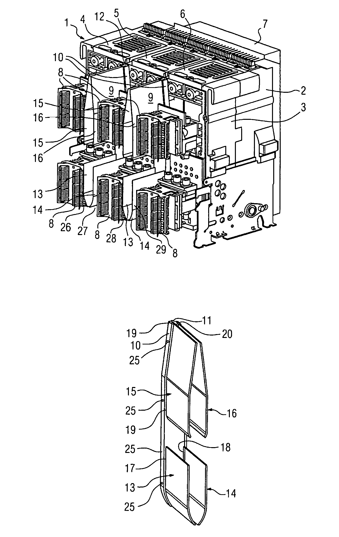
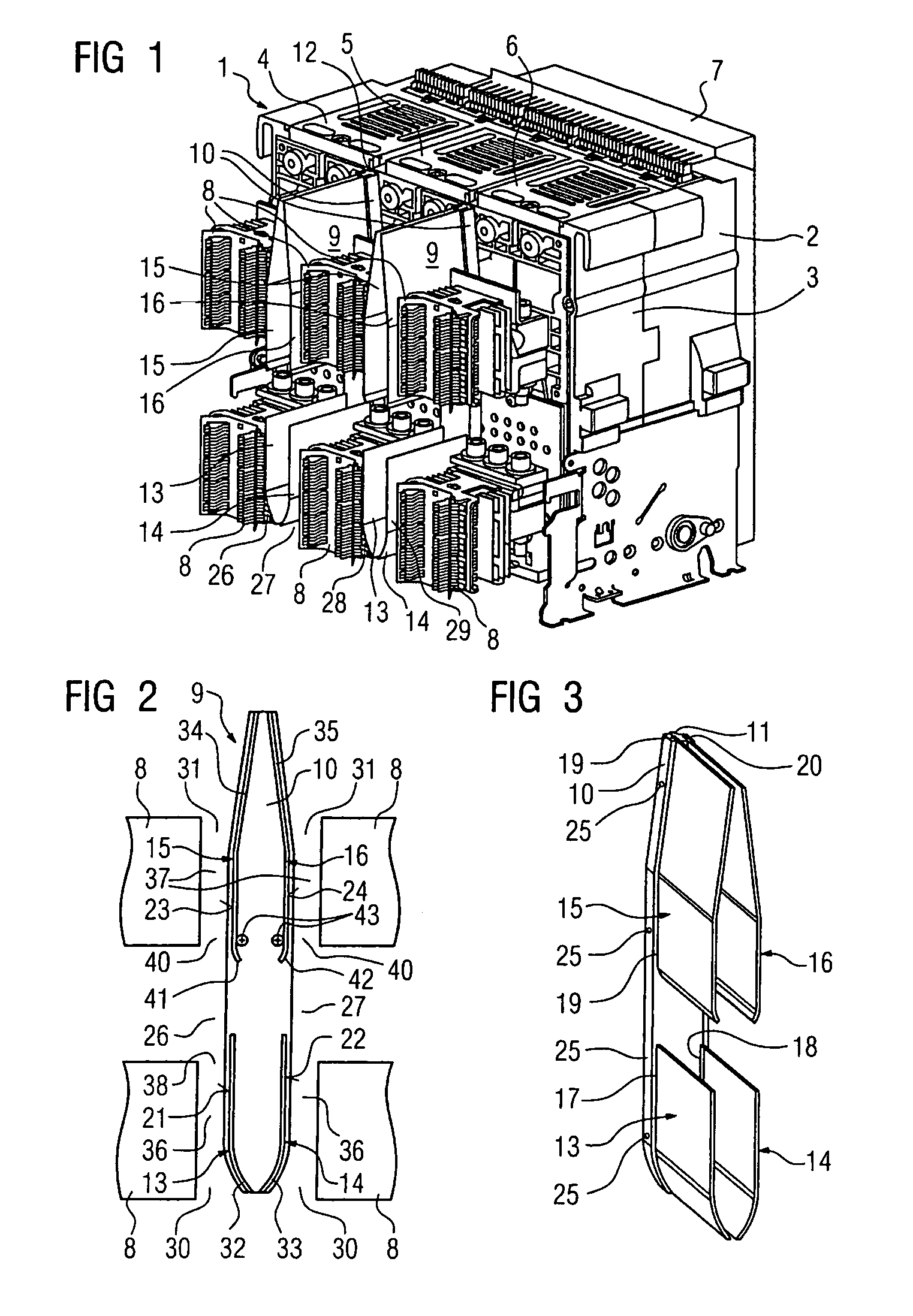
[0016]As is shown in FIG. 1, the low-voltage circuit breaker 1 has a switch pole housing, which includes a front wall 2 and a rear wall 3, for holding the switch poles 4, 5 and 6. For the purposes of an embodiment of the invention, the expression “a switch pole” should in this case be understood as meaning all parts of the circuit breaker which are associated with the main circuit and are equipped with switching pieces for closing and opening. This excludes those parts of the circuit breaker which are used for joint attachment and operation of all of the poles and which are held essentially under a covering shroud 7 of the circuit breaker 1 by way of a supporting mechanism on the front wall 2 of the switch pole housing. Isolating contact systems 8 which are associated in pairs with the switch poles 4, 5 and 6 and are in the form of lower and upper laminate blocks are arranged on the rear wall 3 of the switch pole housing and, during insertion of the circuit breaker into a withdrawab...


PUM


Abstract

An air guidance device is for cooling a switch part of an electrical switch. It includes at least one air guidance element arranged at a distance from the switch part to be cooled, forming at least one air duct which runs vertically when the switch is in the installed position. The air duct includes an inlet area, which points downwards, for cooling air to flow therein, and having an outlet area, which points upwards, for cooling air to flow out thereof. In order to improve the heat dissipation, the air guidance element is shaped such that the inlet area tapers in the direction of the outlet area.

Description

[0001]The present application hereby claims priority under 35 U.S.C. §119 on German patent application number DE 103 26 355.1 filed Jun. 4, 2003, the entire contents of which are hereby incorporated herein by reference.FIELD OF THE INVENTION[0002]The invention generally relates to the field of electrical switches, and is generally applicable to the design configuration of an air guidance device for cooling a switch part.BACKGROUND OF THE INVENTION[0003]In a known electrical switch in the form of a low-voltage circuit breaker, an air guidance device is provided in order to cool pole path chambers. This air guidance device has panels which are provided with depressions on each of their two surfaces. Each of the depressions in this case forms an air guidance element, which is arranged at a distance from the switch part to be cooled, forming an air duct which runs vertically when the switch is in the installed position. The air duct includes an inlet area, which points downwards, for co...

Claims


Application Information

Patent Timeline
Patent Type & Authority Patents(United States)
IPC IPC(8): H01H13/04H01H1/62H01H9/52H01H71/08
CPCH01H9/52H01H1/62H01H71/08
Inventor BUXTON, CLIFFORD A.LOSCH, STEFAN
Owner SIEMENS AG
Why Eureka
Try Eureka