Cable clamp

a technology of cable clamping and clamping rod, which is applied in the direction of manufacturing tools, machine supports, building scaffolds, etc., can solve the problems of unfavorable protection of cable protection members, unfavorable protection of cables, and inability to fix cables to body panels or the like, etc., to achieve convenient attaching operation, minimize space occupied, and convenient positioning

Inactive Publication Date: 2007-04-10
NEWFREY
View PDF15 Cites 67 Cited by
  • Summary
  • Abstract
  • Description
  • Claims
  • Application Information

AI Technical Summary

Benefits of technology

[0012]According to the above cable clamp, a cable, such as an ABS sensor cable is held in the cable clamp by only an operation of positioning the cable on the holder-side portion of the protection member and then closing the cover so that the protective member envelops the cable. This eliminates the need for a separate operation of wrapping the protection member. The anchor and the clamp portion are integrally molded as one piece with hard resin, and the cable protected by the flexible protection member is pressed to the holder by the cover and held by the clamp portion. Thus, the cable is held firmly and protectively. Furthermore, the cover-side portion of the protection member extends from the holder-side portion when the cover is in its open condition, without any contact with the cover. Thus, the cable can be readily positioned on the protection member without widely opening the cover, so as to facilitate an attaching operation in a narrow space.
[0013]In the above cable clamp, the holder may have a pair of walls which form the receiving concavity into a U-shaped configuration. In this case, the cover may be formed to extend from an end of one of the walls through a hinge in parallel to a straight region of the wall to maintain the receiving concavity opened. This structure can minimize a space occupied by the cover in its open state.
[0014]In the above cable clamp, the cover-side portion of the protection member may be formed to have a length which extends in parallel to the cover up to an intermediate height of the cover. Alternatively, the cover-side portion of the protection member may have an upright segment extending parallel to the cover up to the intermediate height of the cover, and an extension segment extending continuously from the upright segment and having an end connected to an upper portion of the cover. The extension segment can block a part of the opening above the upright segment and on the side of the cover to prevent wrong alignment of a cable with the opening. Further, the cable can be adequately guided toward the holder-side portion to reliably position the cable on the holder-side portion of the protective member.
[0015]In the above cable clamp, a portion of the cover for pressing the outer surface of the cable through the protection member may be formed with a protruding rib which presses the cable through the protection member upon closing of the cover to prevent the cable from being axially moved. The protruding rib makes it possible to hold the cable more firmly. In addition to the hinge, each of the first end of the holder and the first end of the cover may be formed with another engagement means adapted to be connected with one another when the cover is in its closed state.
[0016]In the above cable clamp, the anchor may include a base to face a front surface of the workpiece, at least one engagement pawl adapted to be inserted into a mounting hole of the workpiece and brought into engagement with a rear surface of the workpiece, and a pair of resilient wings extending from the base and adapted to resiliently engage the front surface of the workpiece so as to absorb a change in thickness of the workpiece and maintain the engagement function of the engagement pawl. The engagement pawl (or pawls) allows one kind of cable clamp to be used even if the workpiece is varied in thickness.

Problems solved by technology

It is undesirably troublesome to wrap a protection member around the outer surface of a cable, and then hold the cable with the protection member by a cable clamp, and then attach the cable clamp to a body panel.
Although the cable holder disclosed in Publication 1 (Japanese Patent Laid-Open No. 11-69573) is suitable for holding a cable when the cable penetrates a partition wall, it cannot be used to fix a cable to a body panel or the like.
However, that fastener involves the risk of damaging the outer surface of a cable or the like to be held, due to lack of a structure for holding the cable or the like while protecting it from damag.
Thus, a troublesome operation of wrapping a protection member around the outer surface of the cable is undesirably required.
Therefore, that anti-vibration clamp is not suitable for immovably holding a cable or the like.
Thus, the anti-vibration clamp is not suitable for use in a limited space such as a wheel housing or engine compartment.
Thus, the holder is not suitable for use in a limited space such as a wheel housing or engine compartment, due to the need for providing a large space for opening the cover.

Method used


Image

  • Cable clamp
  • Cable clamp
  • Cable clamp

Examples


Embodiment Construction

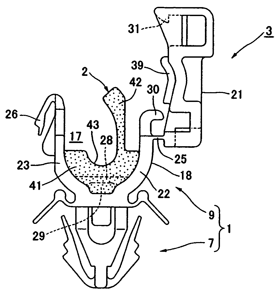
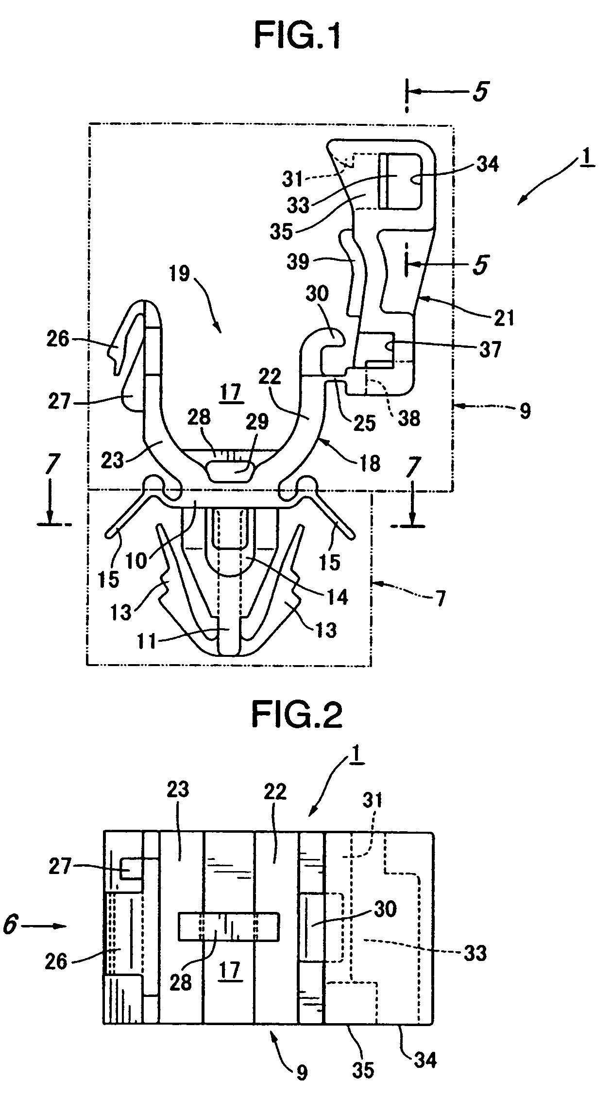
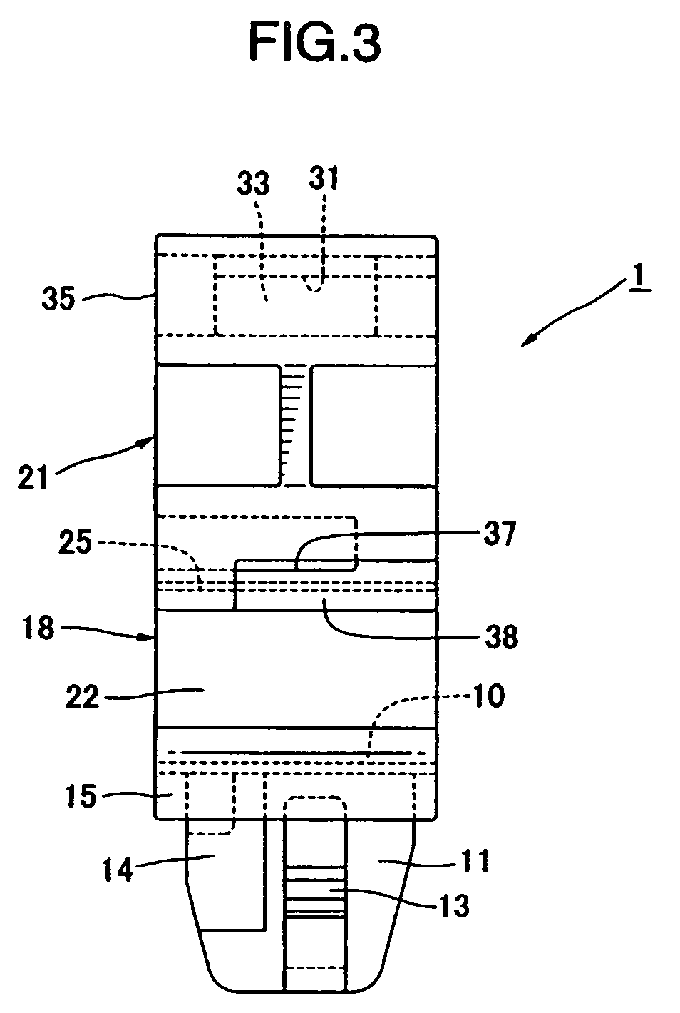
[0034]With reference to the drawings, a cable clamp for clamping a cable, such as a cable of an ABS (Anti-lock Breaking System), according to an embodiment of the present invention will now be described. FIGS. 1 to 12 show a cable clamp according to a first embodiment of the present invention, wherein FIGS. 1 to 8 show a clamp 1, as a primary mold product, made of hard synthetic resin material and having no protection member thereon, and FIGS. 9 and 10 show a cable clamp 3 having a protection member, according to the first embodiment of the present invention. The cable clamp 3 is a secondary mold product (the final product) in which a flexible protection member 2 made of soft resin is formed on a predetermined position of the clamp 1 as the primary product. FIGS. 11 and 12 show an operation of holding a cable 5 to the cable clamp 3 and fixing the cable clamp with the cable to a workpiece such as a body panel 6 of an automobile.

[0035]First, with reference to FIGS. 1 to 8, the primary...


PUM


Abstract

A cable clamp comprises an anchor to be fixed to a workpiece, a clamp portion for clamping a cable, and a flexible protection member for protecting the cable. The anchor and the clamp portion are integrally molded. The clamp portion includes a holder having a concavity, and a cover for closing the concavity. The cover has one end connected to one end of the holder by a hinge. The other end of the cover and the other end of the holder have cooperable latch portions adapted to be latched to one another. The protection member includes a holder-side portion fixed to the holder, and a cover-side portion that extends substantially parallel to the cover in its open state and that is pressed by the cover in its closed state to envelop the outer surface of the cable in cooperation with the holder-side portion.

Description

CROSS-REFERENCE TO RELATED APPLICATION[0001]This application claims the benefit of Japanese Patent Application No. 2003-032014 filed Feb. 10, 2003, incorporated herein by reference.BACKGROUND OF THE INVENTION[0002]The present invention relates to a cable clamp for use, for example, in attaching a cable, such as a signal cable for a speed sensor of an anti-lock braking system (ABS), to a workpiece such as a body panel of an automobile.[0003]In attaching a cable, such as a signal cable for a speed sensor of an anti-lock braking system (ABS), to a workpiece such as a body panel of an automobile, a protection member is wrapped around the outer surface of the cable. Then, the cable with the protection member is held by a cable clamp, and the clamp is attached to the body panel.[0004]Japanese Patent Laid-Open No. 11-069573 (Publication 1) discloses a cable holder for use in wiring an ABS sensor cable from a wheel housing into an engine compartment through a partition wall therebetween. Th...

Claims


Application Information

Patent Timeline
Patent Type & Authority Patents(United States)
IPC IPC(8): F16L3/08F16L3/22F16B2/08B60R16/02F16B2/10H02G3/30H02G3/38
CPCF16L3/1075F16L55/035H02G3/30Y10T403/7176Y10T24/44752H02G3/32
Inventor KAWAI, YASUHIRO
Owner NEWFREY
Why Eureka
Try Eureka